Battery chips precisely machined from back contact solar cell and electrode extraction method
A solar cell and electrode extraction technology, applied in the field of solar cells, can solve the problems of high material cost and high mechanical equipment cost, and achieve the effect of high material cost and mechanical equipment cost, saving processing cost and improving production efficiency.
- Summary
- Abstract
- Description
- Claims
- Application Information
AI Technical Summary
Problems solved by technology
Method used
Image
Examples
Embodiment 1
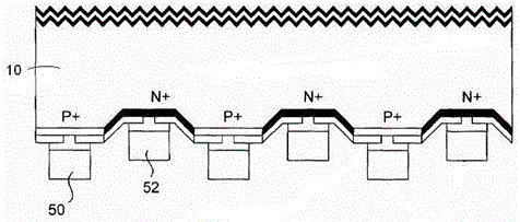
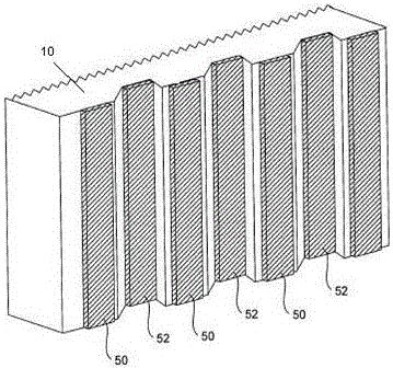
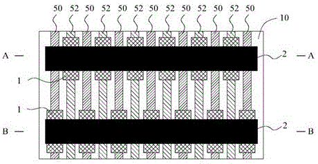
[0038] Such as Image 6 As shown, the back contact solar cell 10 in this embodiment is a 125X125mm specification produced by SUNPOWER in the United States. It is necessary to cut out 18 battery chips with a specification of 32.4X20.9mm at the position shown in the cutting line 4, and the left and right arrangements are horizontal 3. Blocks, 6 blocks up and down vertically, left and right edges reserved silicon chips for use in other sizes, and 3 blocks on the upper edge are led out, such as Figure 7 As shown, the positive terminal 5 of the battery 10 itself can be contacted with the back. The negative terminal is the negative grid that is not covered by the insulating layer 1 by the conductive layer 2 after the positive grid line 50 is covered by the insulating layer 1. Line 52 converges and conducts, and leads to the negative terminals of the 3 blocks below, such as Picture 9 As shown, the negative terminal 6 of the back contact battery 10 can be used. The positive terminal is...
Embodiment 2
[0044] In embodiment 1, if the conductive layer 2 is a non-solderable material, it can be as Picture 10 with Picture 11 As shown, the conductive solderable layer 3 is silk-printed on the soldering points on the conductive layer 2 and the electrode leads are soldered on the solderable layer 3.
Embodiment 3
[0046] Such as Picture 12 with Figure 13 As shown, in Example 1, a 2mm wide conductive profile of a copper tape 8 with a conductive adhesive layer 7 is used to replace the conductive layer 2, and a hot pressing process is used to bond the copper tape 8 with a conductive adhesive layer 7 to the prepared The back of the insulating layer 1 contacts the corresponding positions of the positive and negative electrode lead-out regions of each battery chip to be cut out of the battery 10 to form the positive and negative electrode bus and lead-out electrode ends of each battery chip.
[0047] The production process is as follows:
[0048] 1. First place the back-contact battery 10 with its backlight side up on the screen printing platform, accurately set the grid line insulation coating screen and the back-contact battery 10 alignment points, and then use the mask screen printing process. Silk-print the insulating layer 1 ink paste to the corresponding position on the backlight surface ...
PUM
 Abstract
Description
Claims
Application Information
 - R&D
- Intellectual Property
- Life Sciences
- Materials
- Tech Scout
- Unparalleled Data Quality
- Higher Quality Content
- 60% Fewer Hallucinations
Browse by: Latest US Patents, China's latest patents, Technical Efficacy Thesaurus, Application Domain, Technology Topic, Popular Technical Reports.
© 2025 PatSnap. All rights reserved.Legal|Privacy policy|Modern Slavery Act Transparency Statement|Sitemap|About US| Contact US: help@patsnap.com


