Adjustable current-limiting protection circuit
A current-limiting protection and adjustable technology, which is applied to emergency protection circuit devices, emergency protection circuit devices for limiting overcurrent/overvoltage, circuit devices, etc., can solve circuit burnout, power tube shutdown, power tube large Power consumption and other issues, to achieve the effect of reducing the limit current, simple structure, and strong practicability
- Summary
- Abstract
- Description
- Claims
- Application Information
AI Technical Summary
Problems solved by technology
Method used
Image
Examples
Embodiment 1
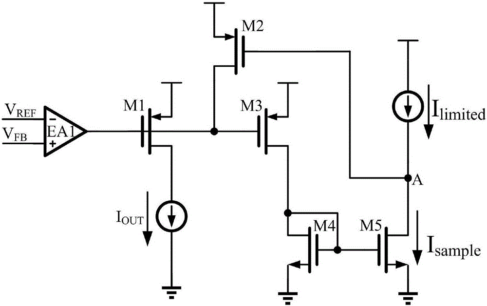
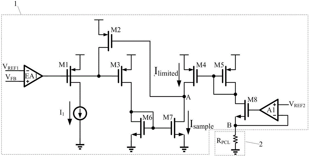
[0017] The specific working principle of the adjustable current-limiting protection circuit described in the first embodiment is as follows:
[0018] Operational amplifier A1, off-chip current limiting resistor R PCL , The eighth MOS transistor M8 constitutes an adjustable current source structure. The positive input terminal of operational amplifier A1 introduces the second reference voltage V REF2 , the op amp A1 in the state of deep negative feedback makes the voltage at point B V B =V REF2 . The off-chip current limiting resistor R PCL Generate current I on RPCL =V REF2 / R PCL , the current flows through the eighth MOS transistor M8. After the current mirror effect of the fifth MOS transistor M5 and the fourth MOS transistor M4, the limit current I limited =M×I RPCL =M×V REF2 / R PCL , M is the current mirror ratio. The output current of the first MOS tube M1 as a power tube is I OUT , through the current sampling of the third MOS transistor M3 as the sampling...
Embodiment 2
[0024] The main idea of the second embodiment is to make the adjustable current limiting protection circuit more precise and easier to use on the basis of the first embodiment.
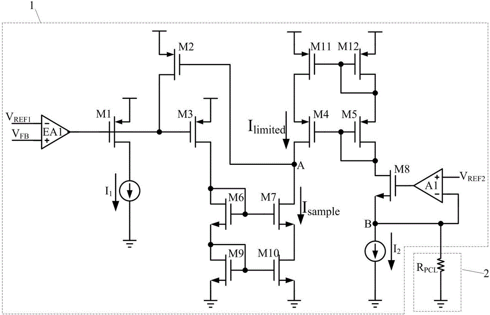
[0025] The specific working principle of the adjustable current-limiting protection circuit described in the second embodiment is as follows:
[0026] The fourth MOS transistor M4, the eleventh MOS transistor M11, the seventh MOS transistor M7, and the tenth MOS transistor M10 form a cascode structure as the sampling current I sample and the limiting current I limited The current comparator, the structure has better current mirroring and comparison, and has better power supply voltage rejection ratio. Second current source I 2 The introduction of min(I RPCL ) = I 2 and min(I limited )=M×I 2 . When the current flowing through the first MOS tube M1 is small and the current limiting protection function is not needed, the off-chip current limiting resistor R is not connected PCL It can make the ...
PUM
 Abstract
Description
Claims
Application Information
 - R&D
- Intellectual Property
- Life Sciences
- Materials
- Tech Scout
- Unparalleled Data Quality
- Higher Quality Content
- 60% Fewer Hallucinations
Browse by: Latest US Patents, China's latest patents, Technical Efficacy Thesaurus, Application Domain, Technology Topic, Popular Technical Reports.
© 2025 PatSnap. All rights reserved.Legal|Privacy policy|Modern Slavery Act Transparency Statement|Sitemap|About US| Contact US: help@patsnap.com


