Method for treating a laser-transparent substrate for subsequently separating the substrate

A laser transparent, substrate technology, applied in laser welding equipment, fine working equipment, stone processing equipment, etc., can solve the problems of unsatisfactory quality of cutting edge or separation surface, long processing time, etc., and achieve small temperature gradient , the effect of slowing down the cooling

Active Publication Date: 2016-06-15
TRUMPF LASERSYST FOR SEMICON MFG
View PDF8 Cites 0 Cited by
  • Summary
  • Abstract
  • Description
  • Claims
  • Application Information

AI Technical Summary

Problems solved by technology

Furthermore, when separating substrates, in particular chemically prestressed glass, disadvantageously long processing ti

Method used


Image

  • Method for treating a laser-transparent substrate for subsequently separating the substrate
  • Method for treating a laser-transparent substrate for subsequently separating the substrate
  • Method for treating a laser-transparent substrate for subsequently separating the substrate

Examples


Embodiment Construction

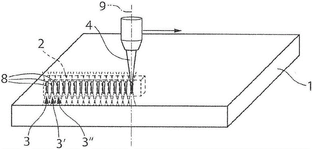
[0036] refer to figure 1 and 2 , a method for processing a laser-transparent substrate 1 , for example chemically hardened glass, for subsequent separation of the substrate 1 along the separation region 2 is described below.

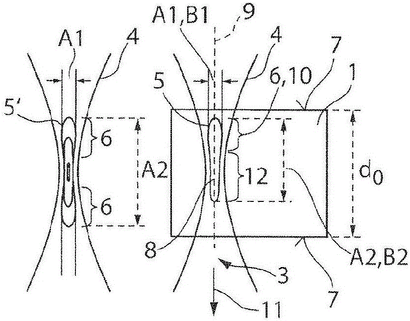
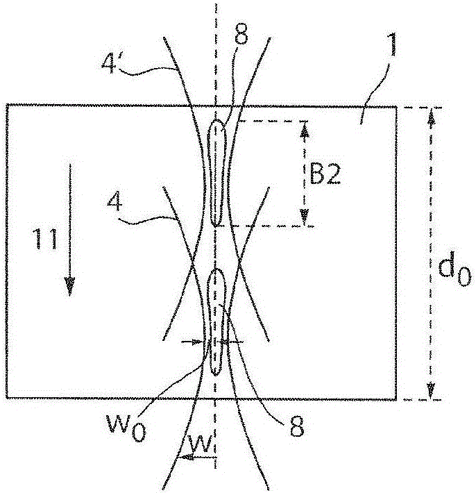
[0037] According to a first method step, the substrate interior is irradiated at the first substrate position 3 with the beam parameters of the laser beam 4 adjusted in such a way that a rod-shaped or pear-shaped constriction in the beam direction 11 is formed in the laser beam 4 A volume region 5 having a fluence or radiation intensity exceeding the threshold for producing modification (reference figure 2 ,right). In this case, the radiation intensity corresponds to the fluence of the laser beam with a defined pulse duration. In particular, the beam parameters of the laser beam 4 are adjusted such that the ratio of the maximum lateral extent A1 of the substrate-surface-side end 6 of the volume region 5 to the maximum longitudinal extent A2 of the vo...


PUM


Abstract

A method for treating a laser-transparent substrate (1) for subsequently separating the substrate (1) along a separating region (2) is proposed, with the following method steps: a.) irradiating the interior of the substrate at a substrate position (3) with beam parameters (zr, w0, l0,lamda) of a laser beam (4) that are set in such a way that in the laser beam (4) there is formed a volume area (5) which is club-shaped or tapers in a pear-shaped manner in the radiating direction (11) and in which a threshold fluence (phi s ) is exceeded to produce a modification, in order to produce a modified region (8) in the interior of the substrate at the substrate position (3), b.) carrying out step a.) at at least one other substrate position (3') to form a separating region (2) comprising the modified regions (8).

Description

technical field [0001] The invention relates to a method for processing a laser-transparent substrate for subsequent separation of the substrate. Background technique [0002] Such a method is known, for example, from EP2258512A1. In the prior art, the substrate is locally melted, so that a structurally weakened region is created inside the substrate. The substrate is broken and thus detached by mechanical effects on the weakened region. [0003] WO 2011 / 025908 A1 discloses a method for cutting chemically hardened glass with laser radiation whose wavelength is transparent to the chemically hardened glass. The laser beam is focused here in the inner tensile region of the chemically hardened glass. [0004] A method for preparing cracks in a substrate is known from WO 2012 / 006736 A2, in which the substrate is irradiated with laser beams such that filaments are produced by self-focusing of the laser beams, along which the substrate can then be split. [0005] Finally, EP149...

Claims


Application Information

Patent Timeline
IPC IPC(8): B23K26/32B28D5/00C03B33/02C03B33/08C03C23/00B23K26/00C03B33/09
CPCC03B33/0222B23K26/32B23K26/50B23K2103/52B28D5/0011
Inventor J·克莱纳D·格罗斯曼
Owner TRUMPF LASERSYST FOR SEMICON MFG
Why Eureka
Try Eureka