Machining device and workpiece machining method

A technology for mechanical processing and processed objects, which is applied in the direction of metal processing equipment, metal processing machinery parts, workpieces, etc., can solve the problems of reduced processing accuracy of processed objects, waste hindering measurement accuracy, and increased manufacturing costs, so as to maintain mechanical Processing accuracy, excellent machining accuracy, and the effect of improving the cooling effect

Inactive Publication Date: 2016-06-15
NAKATA COATING CO LTD
View PDF11 Cites 6 Cited by
  • Summary
  • Abstract
  • Description
  • Claims
  • Application Information

AI Technical Summary

Problems solved by technology

[0011] However, the airbag tear line forming apparatus 200 described in Patent Document 1 is not equipped with a recovery device for waste generated by the cutting process, and no consideration is given to the waste remaining on the tear line.
That is, when the depth of the tear line (fracture groove) is measured using an optical measuring device such as a laser displacement meter, there is a problem that it is difficult to accurately measure the depth of the tear line because the waste interferes with the measurement accuracy.
In particular, it is difficult to measure the depth of the tear line quickly and with high precision at the same time due to the influence of a large amount of waste generated during the cutting process, and to feed back this value to adjust the cutting state
[0012] In addition, the airbag tear line forming device 200 described in Patent Document 1 is provided with a solenoid 208 for reciprocating a cutting tool for a predetermined distance (about 0.5 to 3 mm). The time required to form the linear cut portion becomes longer, so there is a problem that the manufacturing cost increases
[0013] In addition, although the dust collector 501 described in Patent Document 2 intends to recover the dust generated by the hammer body 510b as a machining device, it does not take into account the prescribed antistatic treatment, so even if a cyclone and a recovery tank are installed Etc., static electricity will also be generated so that the dust cannot be recovered efficiently
[0014] Especially in the dry period of winter, a large amount of dust generated is electrostatically attached to the inner walls of cyclones, recovery tanks, etc., making it difficult to efficiently discharge to the outside
[0015] In addition, the cylindrical cover portion 502 surrounding the weight body 510b has rubber bellows portions 502b, 502d as a whole, and is easily elastically deformed not only in the vertical direction but also in the lateral direction, so it is easy to contact the weight body 510b, and as a result, there may be Difficulty in machining with high precision
[0016] In addition, although the mechanical processing device equipped with a waste recovery device described in Patent Document 3 has excellent recovery efficiency of waste of a predetermined size, it does not consider the influence of Joule heat on machine tools in a predetermined environment.
[0017] Therefore, there is a problem that the machine tool is easily deteriorated for a long period of time and in the case where the machining device is driven at high speed at an ambient temperature exceeding 40° C. or, more remarkably, at a temperature exceeding 50° C.
[0018] In addition, if the machine tool deteriorates, there is a problem that the processing accuracy of the workpiece will be significantly reduced.
[0019] In addition, fine particles with an average particle diameter of less than 100 μm or more significantly less than 0.1 to 10 μm tend to remain on the workpiece depending on the type of machining, and become an important factor for measurement errors related to the processing depth.

Method used


Image

  • Machining device and workpiece machining method
  • Machining device and workpiece machining method
  • Machining device and workpiece machining method

Examples


no. 1 approach

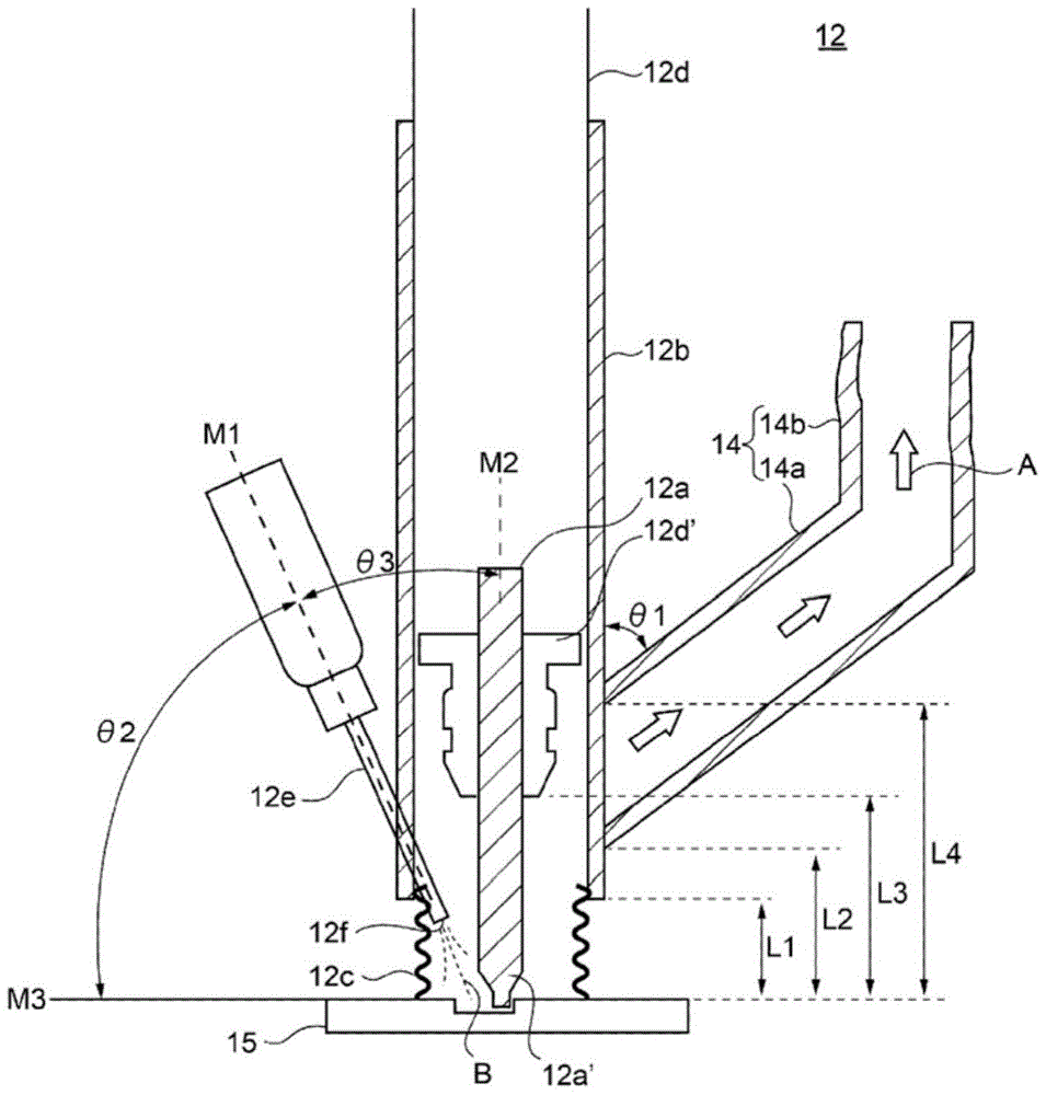
[0060] The first embodiment is as figure 1 As illustrated, it is a machining device 12 that performs predetermined machining on a workpiece 15 with a machine tool 12a housed inside a cylindrical object 12b. The machining device 12 is characterized in that the cylindrical The front end portion of the object 12b is provided with a splash-proof member 12c, which contacts the workpiece 15 without gaps during predetermined machining, and a conveying path 14 is provided on the side of the cylindrical object 12b, which is used for the predetermined machining. And the waste of the processed object 15 produced is sucked, and in the side of the cylinder 12b, an air blowing device 12e is provided at a position symmetrical to the position where the conveying path 14 is provided, and it is used to blow air to the machine tool. 12 at least the front end.

[0061] also, figure 1 is a schematic diagram of the machining device 12, figure 2 It is a schematic diagram showing the waste reco...

no. 2 approach

[0209]The second embodiment is a method of machining a workpiece using a machining device that performs predetermined machining on a workpiece with a machine tool housed inside a cylindrical object. The front end of the cylindrical object is provided with an anti-splash member, which is in contact with the workpiece without gaps during the specified machining, and a conveying path is provided on the side of the cylindrical object, which prevents the workpiece produced due to the specified machining. The waste of the processed object is sucked, and an air blowing port is provided at a symmetrical position on the side of the cylindrical object, which is used to blow air to at least the front end of the machine tool. The machining method of the processed object is characterized in that , including the following steps (1) to (2):

[0210] Step (1), using a machining device, blowing air to at least the front end of the machine tool through the air blowing port, and performing machi...

Embodiment 1

[0266] 1. Formation of fracture grooves for airbags

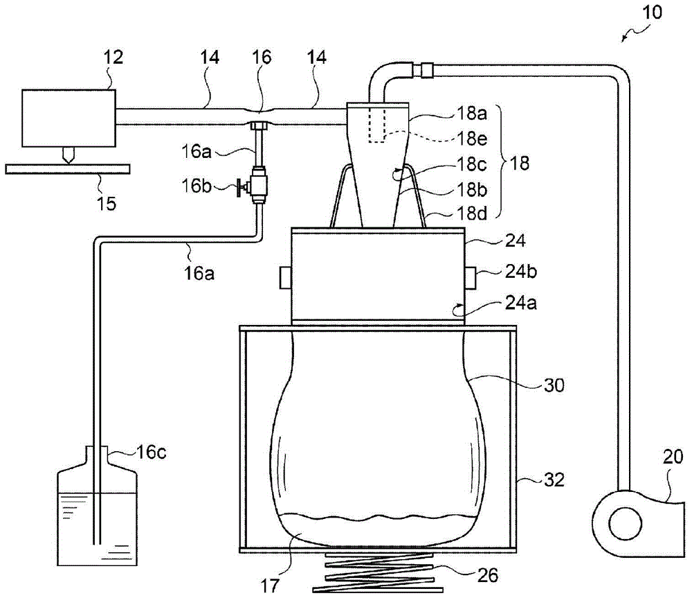
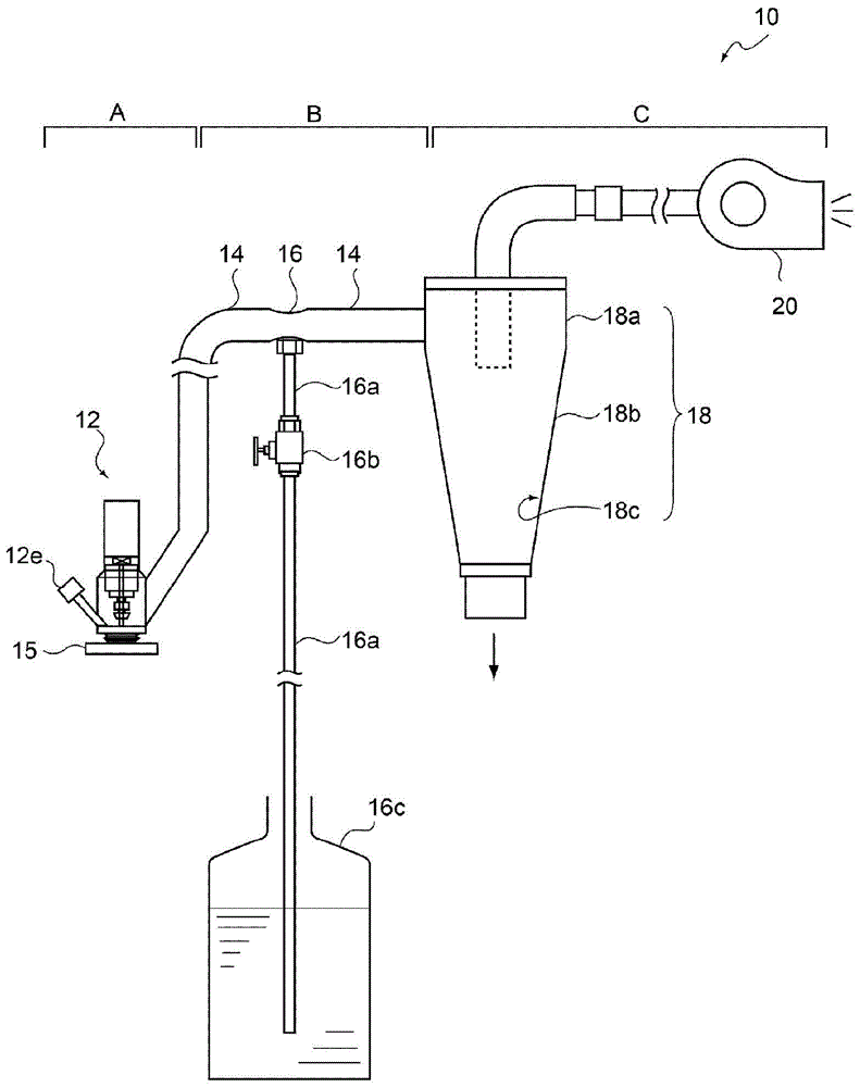
[0267] Prepared to include machining devices (machine tools: end mills) 12 Image 6 The shown airbag fracture groove forming device 100, the machining device (mechanical tool: end mill) 12 such as figure 1 as well as figure 2 As shown, a predetermined waste recycling device 18 including an antistatic treatment device 16 is provided.

[0268] At this time, the linear distance (L1) from the surface of the airbag base material (carbon-containing rigid polypropylene resin) with a thickness of 3 mm to the height position of the air outlet is 10 mm, and similarly, to the lower limit height position of the scattering prevention member The straight-line distance (L2) is 18mm. Similarly, the straight-line distance (L3) to the height position of the lower surface of the chuck of the workpiece is 20mm. Similarly, the straight-line distance (L4) to the upper limit height position of the component for preventing scattering is 30mm....


PUM

PropertyMeasurementUnit
diameteraaaaaaaaaa
heightaaaaaaaaaa
diameteraaaaaaaaaa

Abstract

The purpose of the present invention is to provide a machining device capable of achieving an excellent machining tool cooling effect and high-precision machining and a machining method utilizing said machining device. Provided are a machining device that performs predetermined machining of a workpiece by using a machining tool housed inside a cylindrical body and a machining method that involves the use of said machining device, wherein: a scatter-preventing member that comes into contact with the workpiece without a gap therebetween during the predetermined machining is disposed at the tip of the cylindrical body; a transfer path for sucking in the waste of the workpiece produced during the predetermined machining is provided on a side surface of the cylindrical body; and an air-blowing device for blowing air at least to the tip of the machining tool is disposed on the side surface of the cylindrical body at a position symmetrical to that of the transfer path.

Description

technical field [0001] The present invention relates to a machining device and a machining method of a workpiece using the machining device. In particular, it relates to a machining device in which a machine tool has a long life and has high machining accuracy and measurement accuracy of a workpiece, and a machining method of a workpiece using the machining device. Background technique [0002] Conventionally, as a kind of machining device, an airbag tear line forming device for forming an airbag tear line (tearline) torn when an airbag is deployed in a short time and with high precision has been proposed (see Patent Document 1). . [0003] More specifically, as Figure 9 As shown, the above-mentioned airbag tear line forming device 200 has: a tear line forming support, which houses the skin 220 forming the tear line 220a; a cutting tool 210 including a spindle 209, which is used to form the tear line 220a; a plate 207, which includes a solenoid 208 for reciprocating the c...

Claims


Application Information

Patent Timeline
Patent Type & Authority Applications(China)
IPC IPC(8): B23Q11/00B23C3/00B23C9/00B23Q17/20
CPCB23Q11/006Y02P70/10B23C3/28B23C2215/08B23C2220/64B23C2230/08B23Q11/0816
Inventor 松野竹己
Owner NAKATA COATING CO LTD
Why Eureka
Try Eureka