A flue gas desulphurization denitration method adopting two adsorption columns in series connection and a device therefor

A technology of desulfurization, denitrification, and adsorption tower, which is applied in separation methods, chemical instruments and methods, and separation of dispersed particles, and can solve problems such as increasing operating costs and increasing the amount of ammonia gas

Active Publication Date: 2016-06-22
ZHONGYE-CHANGTIAN INT ENG CO LTD
View PDF14 Cites 37 Cited by
  • Summary
  • Abstract
  • Description
  • Claims
  • Application Information

AI Technical Summary

Problems solved by technology

In addition, SO in flue gas 3 , HF, and HCl will also react with NH3. For denitrification, these side reactions will greatly increase the amount of ammonia gas and increase operating costs.

Method used


Image

  • A flue gas desulphurization denitration method adopting two adsorption columns in series connection and a device therefor
  • A flue gas desulphurization denitration method adopting two adsorption columns in series connection and a device therefor
  • A flue gas desulphurization denitration method adopting two adsorption columns in series connection and a device therefor

Examples


specific Embodiment approach

[0139] The mixing device (M) used in the following examples includes an air pipeline (602), an ammonia pipeline (606), an air helical section (609), an ammonia helical section (610), a mixing section (612) and a mixing Gas outlet (616), wherein the ammonia pipe (606) is inserted (or extended into) the air pipe from one side of the larger diameter air pipe (602), then bent and along the axis of the air pipe (602) along the The air flow direction extends a certain distance L (it is for example 20-80%, more preferably 35-65% of the total length of the mixing device, such as L=0.2-2 meters, preferably 0.3-1.5 meters), the end of the ammonia pipeline (606) The section is an ammonia gas spiral segment (610), and the ammonia gas spiral segment (610) includes m helical ammonia passages separated by m longitudinally extending spiral plates (608) in the ammonia pipeline (606), in addition , the air spiral section (609) corresponding to the ammonia gas spiral section (610) comprises a sp...

Embodiment approach 1

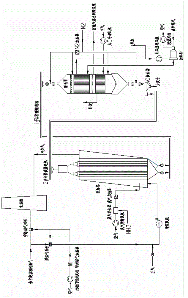
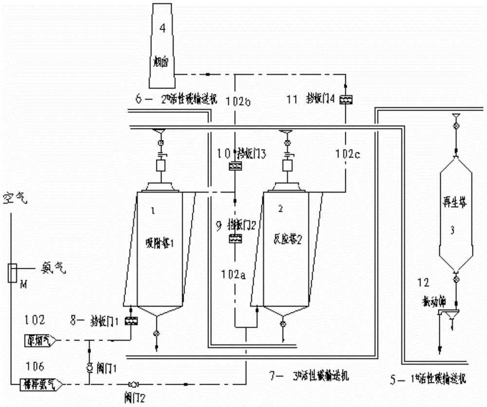
[0150] use figure 1 and the flow shown in Figure 2. Wherein the adsorption tower (1) and the adsorption tower (2) are shown in Figure 2, that is, a single-tower single-bed adsorption tower.

[0151] A desulfurization and denitrification device comprising double adsorption towers in series, comprising

[0152] 1) the first adsorption tower (1) and the second adsorption tower (2) connected in series;

[0153] 2) activated carbon regeneration tower (3) (or analysis tower);

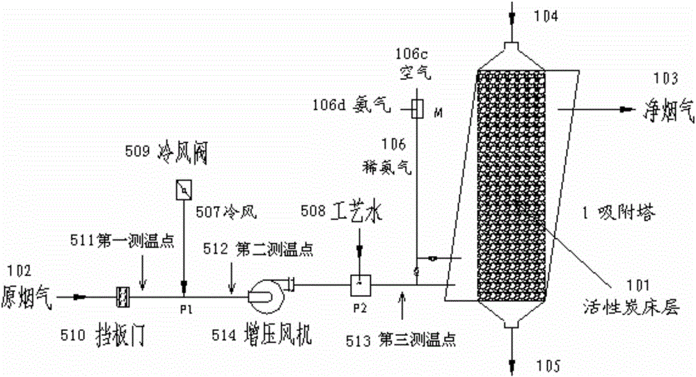
[0154] 3) The raw flue gas conveying flue (102) upstream of the flue gas input port of the adsorption tower (1), on which a cold air inlet (P1) and a process water nozzle (P2) are arranged,

[0155] 4) The primary flue gas pipeline (102a), its front end is connected to the flue gas outlet of the first adsorption tower (1) and its rear end is connected to the second adsorption tower (2) via the second baffle door (9) the intake chamber,

[0156] 5) the secondary clean flue gas pipeline (102b), its front e...

Embodiment approach 2

[0181] use figure 1 And the flow process shown in Fig. 2, but adsorption tower (1) and adsorption tower (2) are as image 3 As shown, that is, a single-tower three-bed adsorption tower.

[0182] A desulfurization and denitrification device comprising double adsorption towers in series, comprising

[0183] 1) the first adsorption tower (1) and the second adsorption tower (2) connected in series;

[0184] 2) activated carbon regeneration tower (3) (or analysis tower);

[0185] 3) the original flue gas delivery flue (102) upstream of the flue gas input port of the first adsorption tower (1), on which a cold air inlet (P1) and a process water nozzle (P2) are provided,

[0186] 4) The primary flue gas pipeline (102a), its front end is connected to the flue gas outlet of the first adsorption tower (1) and its rear end is connected to the second adsorption tower (2) via the second baffle door (9) the intake chamber,

[0187] 5) the secondary clean flue gas pipeline (102b), its f...


PUM


Abstract

A flue gas desulphurization denitration method adopting two activated-carbon adsorption columns (1, 2) in series connection and comprising a flue gas temperature control apparatus and a device therefor are provided. The method includes I) a step of flue gas temperature control and II) a step of desulphurization and denitration, wherein the step of flue gas temperature control comprises (1) a step of subjecting flue gas to first time of cooling by feeding cold air into a flue conveying high-temperature flue gas to activated-carbon adsorption columns from a cold-air inlet at an upstream position (P1) of the flue, (2) spraying cooling water or cold water mist into the flue gas in the flue from a process water spray nozzle at the downstream position (P2) of the position (P1) from which the cold air is fed, and allowing the flue gas to flow along the flue to the adsorption columns, and (3) feeding diluted ammonia gas into the flue gas in the adsorption columns after the flue gas is fed into gas feeding chambers of the adsorption columns. The temperature of the flue gas fed into the adsorption columns is controlled by mixing with the cold air and spraying water. The two activated-carbon adsorption columns (1, 2) in series connection are adopted to significantly increase the denitration efficiency of the device.

Description

technical field [0001] The invention relates to a flue gas desulfurization and denitrification method and device using double activated carbon adsorption towers (also called reaction towers) in series. More specifically, the present invention relates to the adoption of double activated carbon adsorption towers in series and the measures of water spray cooling and cold air cooling are adopted to control the activated carbon bed in the adsorption towers at the upstream or front end of the activated carbon adsorption towers to the flue gas (sintering flue gas). The temperature of the layer is in the range of 110-160°C, preferably controlled in the range of 120-150°C, and the method of spraying ammonia at multiple (position) points in the adsorption tower belongs to the field of sintering flue gas treatment. Background technique [0002] For industrial flue gas, especially sintering machine flue gas in the iron and steel industry, it is ideal to use large-scale dry desulfurizati...

Claims


Application Information

Patent Timeline
Patent Type & Authority Applications(China)
IPC IPC(8): B01D53/75B01D53/76B01D53/60B01D53/72
Inventor 魏进超张震叶恒棣孙英李俊杰
Owner ZHONGYE-CHANGTIAN INT ENG CO LTD
Why Eureka
Try Eureka