Production line for foam floor mats

A production line and floor mat technology, which is applied in the field of floor mat processing, can solve the problems of slow heating speed, slow down of the production process of floor mats, and low degree of automation, and achieve the effects of fast heating speed, improved product quality, and high degree of automation

Active Publication Date: 2016-06-22
ZHEJIANG RUNYANG NEW MATERIAL TECH
View PDF4 Cites 0 Cited by
  • Summary
  • Abstract
  • Description
  • Claims
  • Application Information

AI Technical Summary

Problems solved by technology

The effect of this heating method is poor, the transportation speed of the foaming material in the furnace is slow, the furnace is large in volume, and the heat loss at the inlet and outlet of the heating furnace will have a huge impact on the foaming effect in the furnace
In addition, winding and shaping and cutting to length need to be transferred to independent equipment for separate implementation, which further slows down the production process of floor mats, which is not conducive to the improvement of production efficiency
[0003] For example, the notification number is CN1799809A, which discloses a radiation cross-linked polyolefin foaming equipment, which uses horizontal preheating and vertical foaming furnaces to heat and foam polyolefin materials, but it has the following problems: 1. Heating speed Slow, high heating energy consumption, the hot gas in the furnace cannot be fully utilized during the heating process
2. The vertical foaming section is longer. When the foaming material is vertically foaming, it will be elongated under the action of gravity. An expansion device needs to be installed inside, which will cause damage to the surface of the material when the foaming material is expanded. affect the quality of the finished product
3. After the foaming is completed, the material needs to be transferred to the next step of processing, the degree of automation is low, and the amount of manual labor is high

Method used


Image

  • Production line for foam floor mats
  • Production line for foam floor mats
  • Production line for foam floor mats

Examples


Embodiment 1

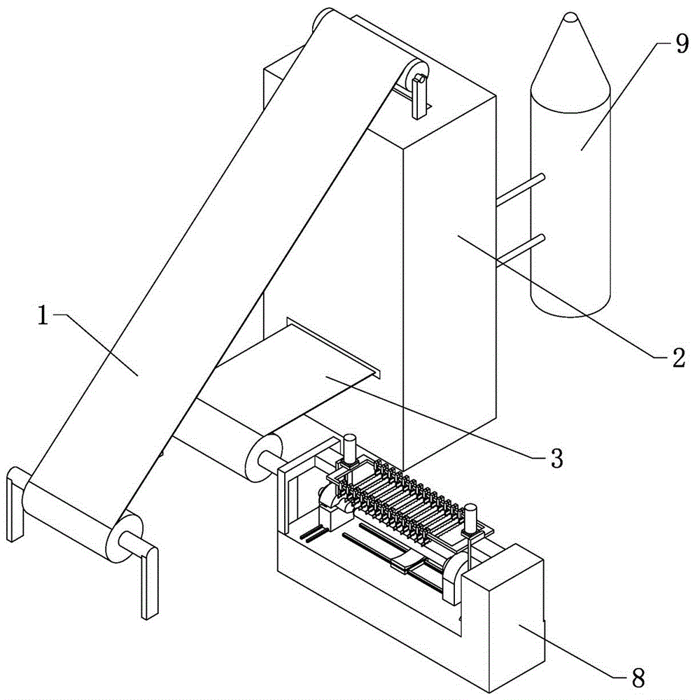
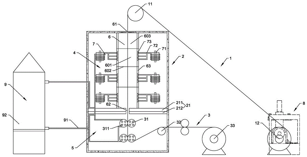
[0034] according to Figure 1 to Figure 5As shown, a foaming floor mat production line includes: a feeding device 1, a processing chamber 2, a receiving device 3, a cutting device 8 and a cooling device 9;

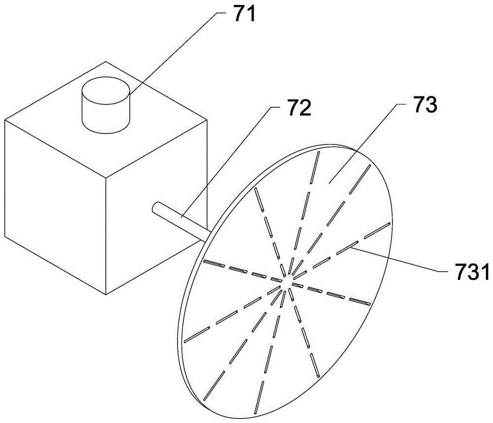
[0035] The processing chamber 2 includes: a heating zone 4 for material foaming and a cooling zone 5 for material shaping, the heating zone 4 and the cooling zone 5 communicate with each other, and the opening between the heating zone 4 and the cooling zone 5 is provided. Belt 21; the heating zone 4 comprises, the foaming channel 6 of elongated cross-section and the heating system 7 used for heating the material in the foaming channel 6, and the two ends of the foaming channel 6 along the material conveying direction are respectively provided with slit-shaped The material inlet 61 and the material outlet 62, the inner wall of the foaming channel 6 is provided with a reflective layer 63; the heating system 7 includes a wave source transmitter 71, a waveguide 72 and an energ...

Embodiment 2

[0049] The difference from the first embodiment above is that the foaming channel 6 includes a resonant region 601 . The resonance area 601 has a rectangular three-dimensional structure, and the energy feeding ports 73 are symmetrically distributed on two horizontally opposite side walls of the resonance area 601 , and each side wall is provided with a plurality of energy feeding ports 73 . The side lengths of the resonance region 601 and the vibration frequency f of the waves emitted by the wave source transmitter 71 are 915MHz, the power is 100kw, and the length, width and height of the resonance region 601 are 150cm, 50cm and 100cm respectively. A temperature controller is provided in the resonance area 601, the temperature controller includes a temperature detector and a power regulator, and controls the temperature in the resonance area 601 to be 160°C.


PUM

PropertyMeasurementUnit
lengthaaaaaaaaaa
thicknessaaaaaaaaaa

Abstract

The invention relates to the field of floor mat processing, and specifically relates to a production line for foam floor mats. The production line for the foam floor mats comprises a loading device, a processing chamber, a receiving device, a cutting device and a cooling device, wherein the processing chamber comprises a heating area and a cooling area, the heating area and the cooling area are mutually communicated, and an isolation belt is arranged at the junction of the heating area and the cooling area; the heating area comprises a foaming channel and a heating system, and a reflecting layer is arranged on the inner wall of the foaming channel; the heating system comprises a wave source transmitter, a waveguide tube and an energy feed port; the cutting device comprises a rack, a rotating device, a cutting table and a control mechanism; and the cooling device comprises a cooling tube and a cooler, and the cooling tube is wound outside the wave source transmitter and connected with the cooler.

Description

technical field [0001] The invention relates to the field of floor mat processing, in particular to a foamed floor mat production line. Background technique [0002] At present, the main production steps of polyolefin foam floor mats include unwinding, foaming, shaping, winding and slitting. The foaming furnace of the existing foaming furnace uses hot air, steam, etc. to provide the high-temperature environment required for foaming. Usually, the foaming furnace heats up the furnace by heat conduction through electric heating or fuel heating to achieve foaming. temperature. The effect of this heating method is poor, the transportation speed of the foaming material in the furnace is slow, the furnace chamber is large, and the heat loss at the inlet and outlet of the heating furnace will have a huge impact on the foaming effect in the furnace. In addition, winding and shaping and cutting to length need to be transferred to independent equipment for separate implementation, wh...

Claims


Application Information

Patent Timeline
Patent Type & Authority Applications(China)
IPC IPC(8): B29C69/00B29C44/20B29C44/34B29C44/46B29C44/60B29K23/00B29L7/00
CPCB29C44/20B29C44/3415B29C44/3419B29C44/467B29C44/60B29C69/001B29K2023/00B29L2007/00
Inventor 张镤
Owner ZHEJIANG RUNYANG NEW MATERIAL TECH
Why Eureka
Try Eureka