Heat pipe and ultrasonic wave combined ice preventing and removing device and method utilizing waste heat of aircraft engine

An aircraft engine and ultrasonic technology, applied in deicing devices, aircraft parts, transportation and packaging, etc., can solve the problems of reducing the adhesion between the ice layer and the surface of the wing, reducing the time for heat pipes to melt ice, and reducing energy consumption. To achieve the effect of guaranteed performance, strong implementability and prevention of icing

Inactive Publication Date: 2016-06-22
NANJING NORMAL UNIVERSITY
View PDF7 Cites 12 Cited by
  • Summary
  • Abstract
  • Description
  • Claims
  • Application Information

AI Technical Summary

Problems solved by technology

[0006] Aiming at the shortcomings of the hot gas anti-icing technology used in the flight process of the existing aircraft, such as long deicing time and large energy consumption, the present invention proposes a heat pipe ultrasonic combined anti-icing and deicing device and method using the waste heat of the aircraft engine. The combined anti-icing and deicing On the basis of ultrasonic deicing technology, the ice device is equipped with a heat pipe anti-icing system, which can effectively prevent the leading edge and surface of the wing from icing in real time during flight; At the same time, it provides favorable conditions for deicing the heat pipe, reduces the time for the heat pipe to melt ice, and greatly reduces energy consumption

Method used


Image

  • Heat pipe and ultrasonic wave combined ice preventing and removing device and method utilizing waste heat of aircraft engine
  • Heat pipe and ultrasonic wave combined ice preventing and removing device and method utilizing waste heat of aircraft engine
  • Heat pipe and ultrasonic wave combined ice preventing and removing device and method utilizing waste heat of aircraft engine

Examples


Embodiment Construction

[0033] The present invention will be further described below in conjunction with the drawings and embodiments.

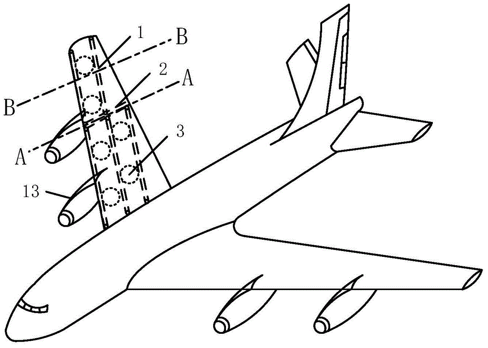
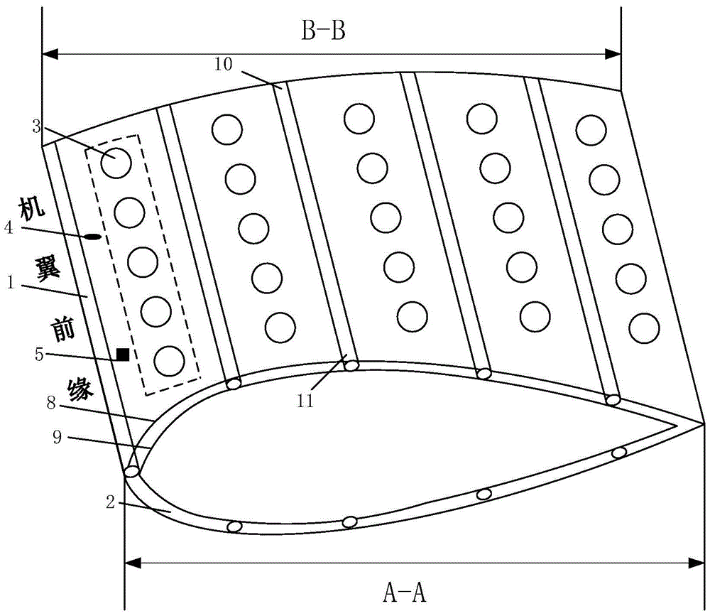
[0034] The heat pipe ultrasonic combined anti-icing and deicing device of this embodiment includes a heat pipe anti-icing system, an ultrasonic oscillation deicing system, a program control system, an atmospheric temperature sensor 4 for detecting the outside air temperature, and an outer skin 9 for detecting the airfoil. The icing intensity signal 5 of the thickness of the ice layer on the surface. The atmospheric temperature sensor 4 and the icing intensity signal 5 are both installed on the outer surface of the outer skin 8 of the wing. The overall structure of the combined anti-icing and deicing device of this embodiment is close to the airfoil skin, and does not affect the aerodynamic shape of the aircraft; it can effectively and uniformly deicing, and the overall distribution is evenly distributed (specifically, Figure 1-2 Shown).

[0035] Among them, the heat p...


PUM


Abstract

The invention provides a heat pipe and ultrasonic wave combined ice preventing and removing device and method utilizing waste heat of an aircraft engine. The device comprises a heat pipe ice-preventing system, an ultrasonic oscillation ice removing system, a program control system, an atmospheric temperature sensor and an icing strength annunciator. The heat pipe ice-preventing system comprises a communicating pipe installed at the tail portion of the engine to absorb exhaust waste heat and a heat pipe bank bundle with an evaporation section connected with the communicating pipe. The ultrasonic oscillation ice removing system comprises an ultrasonic generator and an ultrasonic transducer unit connected with the output end of the ultrasonic generator through a connecting cable. The program control system automatically controls on and off between the heat pipe bank bundle and the communicating pipe and starting or stopping of the ultrasonic generator according to a temperature signal and an icing strength signal. By means of the synergistic effect of heat pipes and ultrasonic waves, preventing and removing can be combined, compared with a method for removing ice simply through ultrasonic waves, the icing phenomenon of wings is greatly reduced, the flying stability of an aircraft is ensured, and a system is safe and reliable.

Description

Technical field [0001] The invention relates to an anti-icing device, in particular to a heat pipe ultrasonic combined anti-icing and deicing device and method using aircraft engine waste heat, and belongs to the technical field of aircraft anti-icing and deicing. Background technique [0002] Icing is one of the main causes of aircraft flight accidents. According to statistics, about 9% of aircraft accidents are caused by icing, especially the icing on the leading edges of aircraft wings and tails, which will increase airfoil drag and lift. Descent, the reduction of the critical angle of attack, and the deterioration of maneuverability and stability will cause the aircraft to lose control of its maneuverability during take-off and landing, and eventually cause serious flight accidents. [0003] Aiming at the problem of anti-icing and deicing of wings and tail fins during flight, hot air anti-icing technology is widely used at present, that is, during flight, the use of hot air dra...

Claims


Application Information

Patent Timeline
Patent Type & Authority Applications(China)
IPC IPC(8): B64D15/00B64D15/04
CPCB64D15/00B64D15/04
Inventor 李栋朱琳赵孝保华君叶张敏
Owner NANJING NORMAL UNIVERSITY
Why Eureka
Try Eureka