Check patentability & draft patents in minutes with Patsnap Eureka AI!

Hydraulic overload protection device and mechanical press with hydraulic overload protection device

An overload protection and press technology, applied in the direction of presses, fluid pressure actuating devices, mechanical equipment, etc., can solve the problems of poor working stability, long time required for the press to resume normal work, slow response to unloading action, etc. Improved accuracy and reliability, debugging and user-friendly effects

Inactive Publication Date: 2016-06-22
杭震
View PDF9 Cites 3 Cited by
  • Summary
  • Abstract
  • Description
  • Claims
  • Application Information

AI Technical Summary

Problems solved by technology

[0005] (1) The pneumatic oil pressure booster pump moves frequently and is easily damaged;
[0006] (2) The actual working tonnage cannot be known when overloading occurs;
[0007] (3) The working stability is poor, and the press is often unloaded in advance when the nominal force is less than;
[0008] (4) It takes a long time for the press to return to normal work after overloading occurs
[0010] Although this device omits the pneumatic oil pump and partially solves the above-mentioned technical problems, a technical problem was discovered during the development process: in order to make the pressure of the hydraulic pad oil of the slider reach the required pre-pressure from the initial pressure, a booster piston is required. Drive the plunger to squeeze the oil in the system as much as possible, which means that the plunger will enter the booster chamber too much; communicated with pressure relief chamber
This contradiction will cause the unloading action to respond slowly when the press is overloaded

Method used


Image

  • Hydraulic overload protection device and mechanical press with hydraulic overload protection device
  • Hydraulic overload protection device and mechanical press with hydraulic overload protection device
  • Hydraulic overload protection device and mechanical press with hydraulic overload protection device

Examples


Embodiment Construction

[0035] In order to better understand and implement the present invention, the present invention will be described in detail below in conjunction with the drawings of the first embodiment.

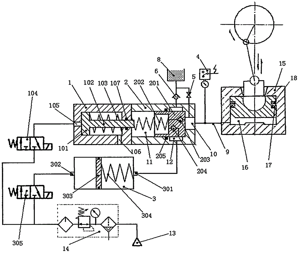
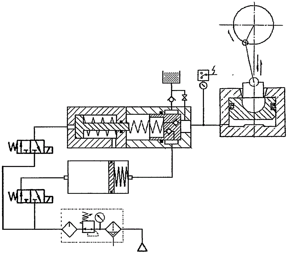
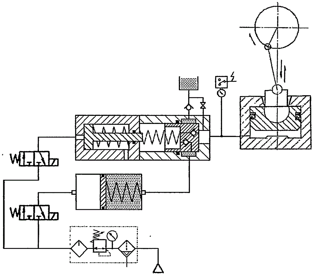
[0036] see figure 1 , the first embodiment of the present invention includes a pneumatic supercharger 1, an overload relief valve 2, a gas spring accumulator 3, a pressure transmitter 4, an exhaust valve 5, an oil suction check valve 6, a solenoid valve ( 104,305), oil tank 8, high-pressure oil pipe 9, filter pressure regulating assembly 14 and air source 13, form a closed circuit with slide block 15 hydraulic cushion 16, take described overload relief valve 2 as the center:

[0037] ①The balance piston 201 is close to the high-pressure chamber 10 under the action of the back pressure spring 202, and its sealing surface isolates the pressure relief chamber 12 from the high-pressure chamber 10; there are two check valves inside the balance piston 201: one check valve 203 communicates with th...


PUM


Abstract

The invention discloses a hydraulic pressure overload protection device for a gas spring accumulator with the function of an oil pump, which forms a closed loop with the hydraulic cushion of a sliding block. The booster piston drives the plunger to squeeze the oil in the system once, so that the system pressure reaches the required pre-pressure from the initial pressure. Under the action of this pressure, the balance piston ensures that the high pressure chamber is isolated from the pressure relief chamber. When the press is overloaded, the pressure transmitter sends out a signal to make the solenoid valve act to switch the gas path, the booster piston drives the plunger to move quickly to reset, the oil pressure in the back pressure chamber drops, the balance piston is pushed open, and the high pressure chamber and pressure relief chamber Connected, the oil in the slider hydraulic pad is quickly released into the gas spring accumulator to complete the overload relief protection action. When the pressure transmitter uses a pressure sensor, the pressure digital signal of the slider hydraulic pad can be sent to the PLC in the control box of the press. After calculation and transformation, the working tonnage of the press can be displayed in real time, and the overload tonnage can be displayed when it is overloaded.

Description

technical field [0001] The invention relates to overload protection of a press, in particular to a hydraulic overload protection device for a mechanical press. The invention also relates to a mechanical press equipped with such a device. Background technique [0002] The mechanical press is a kind of metal forming machine. In actual use, the slider will be overloaded due to various reasons. The main reasons are: improper selection of press model tonnage, inaccurate mold adjustment or installation, increase in blank thickness or increase in material strength; change in lubricating oil quality, poor lubrication, blunt die cutting edge and foreign matter falling into the cavity, etc. . This often results in equipment damage or personal injury. [0003] In order to solve this problem, mechanical presses generally use various forms of overload protection devices to limit the force of the slider. Taking the common pneumatic hydraulic overload protection device in my country's ...

Claims


Application Information

Patent Timeline
IPC IPC(8): F15B1/027B30B15/28F15B1/24
CPCF15B1/027B30B15/281F15B1/24
Inventor 杭震
Owner 杭震
Features
  • R&D
  • Intellectual Property
  • Life Sciences
  • Materials
  • Tech Scout
  • Unparalleled Data Quality
  • Higher Quality Content
  • 60% Fewer Hallucinations
Learn More