
Microwave attenuator

A microwave attenuation and metal wire technology, which is applied to waveguide-type devices, circuits, electrical components, etc., can solve the problems that attenuators cannot take into account, it is difficult to achieve continuous changes in attenuation, and the structure is complex. integrated effects

Inactive Publication Date: 2016-06-22
PEKING UNIV
View PDF4 Cites 15 Cited by
  • Summary
  • Abstract
  • Description
  • Claims
  • Application Information

AI Technical Summary

Problems solved by technology

With the development of microelectronics technology, high-performance attenuators need to have the characteristics of small size, easy integration, and wide operating frequency range. The existing attenuator structure usually cannot take into account
In addition, the variable attenuator that can freely change the loss is also one of the research focuses in this field. The existing implementation methods use passive devices and active devices. The former uses switches to adjust the loss, which is difficult to achieve continuous changes in attenuation; The latter has a complex structure, including multiple PIN tubes or FETs and other active devices

Method used


Image

  • Microwave attenuator
  • Microwave attenuator
  • Microwave attenuator

Examples


Embodiment 1

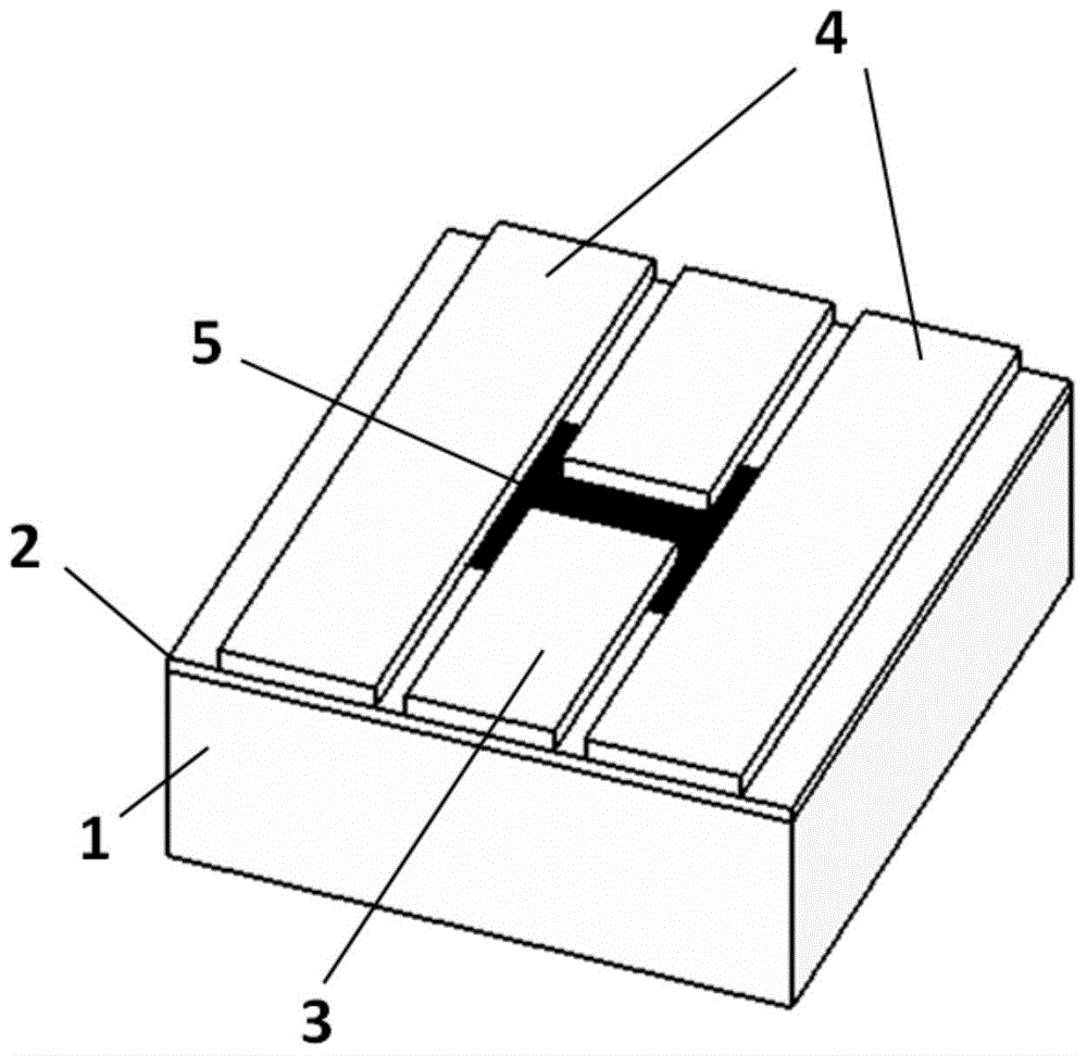
[0015] Embodiment 1: A graphene coplanar waveguide fixed attenuator. Such as figure 1 As shown, it includes a silicon substrate 1 , a silicon dioxide dielectric layer 2 , a copper or aluminum wire 3 , a copper or aluminum ground wire 4 and a graphene film resistor 5 .

[0016] During production, the silicon wafer is first oxidized, and silicon dioxide with a thickness of about 20 μm is formed on the surface of the silicon wafer as a dielectric layer; secondly, a single-layer graphene is prepared and etched on the dielectric layer, and the shape is about 360 μm in width and 300 μm in length Afterwards, prepare the wire and the ground wire, the wire width is 190 μm, leave a 20 μm long gap in the middle, the center of the gap coincides with the center of the graphene film resistor, the ground wire is 250 μm wide, and 20 μm away from the wire.

[0017] The specific process for preparing single-layer graphene can be grown by chemical vapor deposition (CVD) or mechanically exfoliat...


PUM


Abstract

The present invention discloses a microwave attenuator, belonging to the technical field of microwave passive components. The microwave attenuator comprises a substrate, a dielectric layer, a metal wire, a metal ground wire, and a thin film resistor which is a single layer graphene. The microwave attenuator disclosed by the invention has the advantages of easy integration, wide working frequency band and can be used as a fixed attenuator and a variable attenuator, and an electrically controlled or optically controlled variable attenuator can be realized.

Description

technical field [0001] The invention belongs to the technical field of microwave passive devices, and in particular relates to a microwave attenuator. Background technique [0002] Attenuator is a commonly used microwave passive device, which is widely used in wireless communication, radar, device testing and other fields. It can introduce a predetermined attenuation to the propagated electrical signal within the specified frequency range. Its main purpose is to adjust the level of the input signal to adapt to the level requirements of various ports. With the development of microelectronics technology, high-performance attenuators need to have the characteristics of small size, easy integration, and wide operating frequency range, and the existing attenuator structures usually cannot take care of them. In addition, the variable attenuator that can freely change the loss is also one of the research focuses in this field. The existing implementation methods use passive devic...

Claims


Application Information

Patent Timeline
Patent Type & Authority Applications(China)
IPC IPC(8): H01P1/22
Inventor 秦樵风王紫东贾越辉彭沛任黎明傅云义
Owner PEKING UNIV
Learn More