
Lasers and Optical Line Terminations for Passive Optical Networks

A passive optical network and optical line terminal technology, applied in the field of lasers and optical line terminals, can solve the problems of reducing the performance of the WDM-PON system, limiting the system performance, receiving bit error rate, and enhancing the nonlinear effect, so as to reduce costs and reduce costs. Power consumption, high wavelength utilization, effect of reducing residual intensity noise

Active Publication Date: 2019-02-01
ALCATEL LUCENT SHANGHAI BELL CO LTD
View PDF3 Cites 0 Cited by
  • Summary
  • Abstract
  • Description
  • Claims
  • Application Information

AI Technical Summary

Problems solved by technology

[0005] 2) Due to the randomness of broadband ASE light, the characteristics similar to noise and the bandwidth of the channel after spectrum cutting is very wide, it will cause chromatic dispersion, and will seriously reduce the performance of the WDM-PON system with spectrum cutting (for example, intersymbol interference, limited power budget)
[0006] 3) Chromatic dispersion enhances the residual intensity noise (EIN: Excess IntensityNoise) caused by ASE and ASE beating, thus limiting the performance of the system and increasing the receiving bit error rate
[0008] 5) Due to the wide channel bandwidth after spectrum cutting, the spectrum utilization rate is low
[0009] 6) There is multi-mode coexistence in the channel after cutting, which leads to the enhancement of nonlinear effect

Method used


Image

  • Lasers and Optical Line Terminations for Passive Optical Networks
  • Lasers and Optical Line Terminations for Passive Optical Networks
  • Lasers and Optical Line Terminations for Passive Optical Networks

Examples


Embodiment Construction

[0054] In the following detailed description of the preferred embodiment, reference is made to the accompanying drawings which form a part hereof. The accompanying drawings show, by way of example, specific embodiments in which the invention can be practiced. The illustrated embodiments are not intended to be exhaustive of all embodiments in accordance with the invention. It is to be understood that other embodiments may be utilized and structural or logical changes may be made without departing from the scope of the present invention. Accordingly, the following detailed description is not limiting, and the scope of the invention is defined by the appended claims.

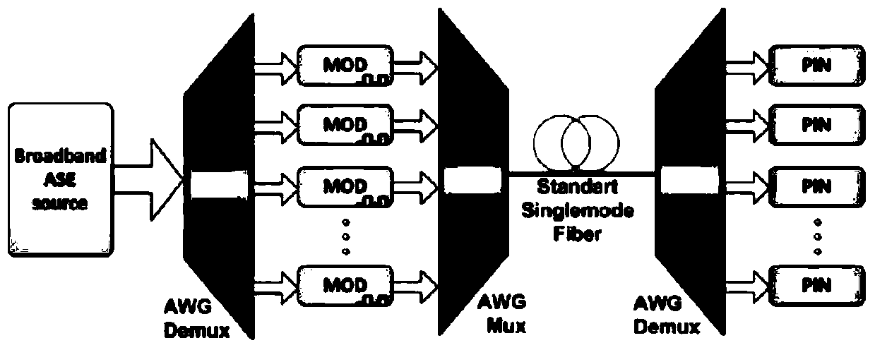
[0055] figure 1 A schematic diagram of a WDM-PON system according to the principle of spectrum cutting in the prior art is shown. Since the spectrum cutting has been described in the background technology section, details will not be repeated here.

[0056] The present invention proposes a laser for passive opti...


PUM


Abstract

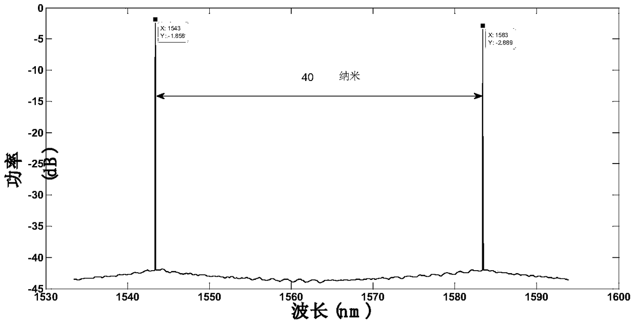
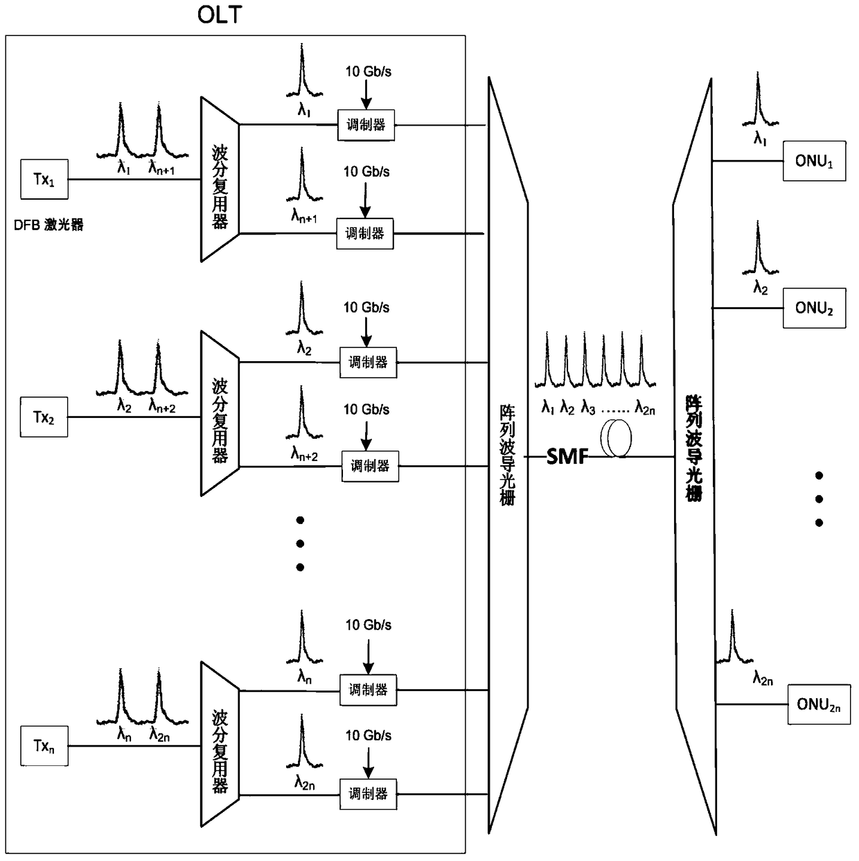
The present invention relates to a laser for a passive optical network and optical line terminal with the laser. A distributed feedback laser is made with an indium, arsenic, nitrogen and gallium alloy as an active layer material. Through tuning the component of each element in the indium, arsenic, nitrogen and gallium alloy, the laser produces laser comprising two coherent laser wavelengths at the same time, and the two coherent laser wavelengths have the same amplitude, signal to noise ratio and line width. The laser wavelengths generated by the laser are increased with the increase of the nitrogen element in the indium, arsenic, nitrogen and gallium alloy and are increased with the increase of the temperature of the indium, arsenic, nitrogen and gallium alloy. With the random distribution of the nitrogen atom in the indium, arsenic, nitrogen and gallium alloy and the fluctuation of the content of the nitrogen element, the broadening of a guide band bottom is generated, thus a nitrogen localized state cluster is caused near the guide band bottom to generate direct lasing. Based on the optical line terminal of the laser provided by the invention, the laser and the optical line terminal have the advantages of low cost and low power consumption, and the network upgrade and tenability are convenient.

Description

technical field [0001] The present invention relates to optical communication technology, in particular to a laser used in a communication system for a passive optical network and an optical line terminal. Background technique [0002] Wavelength Division Multiplexing Passive Optical Network (WDM-PON: Wavelength Division Multiplexing Passive Optical Network) is considered to be an evolution version for the next generation PON (NG-PON2: Next Generation PON). Through dedicated uplink and downlink wavelength allocation, WDM technology provides virtual point-to-point fiber connections for multiple users. However, the extensive development of WDM-PON still needs to overcome some obstacles. One of the most pressing issues is the design of the optical line terminal (OLT: Optical Line Terminal) laser transmitter. Since the Full Service Access Network Forum (FSAN: Full Service Access Networks) has recently standardized the system requirements of WDM-PON, in this WDM-PON system, NG-...

Claims


Application Information

Patent Timeline
Patent Type & Authority Patents(China)
IPC IPC(8): H01S5/323H01S5/06H01S5/12
Inventor 孙晓昌庆江
Owner ALCATEL LUCENT SHANGHAI BELL CO LTD
Learn More