
External cold water descaling device for direct-current converter valve cooling system and method

A DC converter valve and cooling system technology, applied in the direction of descaling and water softening, chemical instruments and methods, electrochemical water/sewage treatment, etc. Solve problems such as tower heat exchange efficiency and cooling tower coil scaling, achieve obvious descaling effect, high descaling efficiency, and reduce cleaning costs

Active Publication Date: 2016-06-29
STATE GRID CORP OF CHINA +2
View PDF4 Cites 7 Cited by
  • Summary
  • Abstract
  • Description
  • Claims
  • Application Information

AI Technical Summary

Problems solved by technology

[0006] In the field of converter valves, the current monitoring items for the water quality of the DC converter valve cooling system mainly include: conductivity, pH (only a few converter stations monitor), dissolved oxygen, temperature, these data indicators are few, and for Regular testing has led to the problem of fouling of cooling tower coils in many domestic converter stations
The fouling of the cooling tower coil will greatly reduce the heat transfer efficiency of the cooling tower, resulting in a high temperature of the internal cooling water. If the margin of the cooling tower is insufficient, it will easily cause the valve temperature to be too high and trip, causing serious consequences
[0007] In the water treatment industry, there have been small electrochemical descaling instruments. However, they mainly adopt a circular tube structure, and the amount of descaling is small, and it is inconvenient to clean. It is difficult to apply to the cooling system of the diverter valve with a large amount of water. External cooling water descaling

Method used


Image

  • External cold water descaling device for direct-current converter valve cooling system and method
  • External cold water descaling device for direct-current converter valve cooling system and method
  • External cold water descaling device for direct-current converter valve cooling system and method

Examples


Embodiment Construction

[0033] The specific implementation manners of the present invention will be further described in detail below in conjunction with the accompanying drawings.

[0034] DC transmission converter valve cooling system, including main circulating water pump, heating tank, air radiator, main filter, converter valve and degassing tank; outlet of said main circulating water pump, heating tank, air radiator, main filter, The diverter valve, the degassing tank and the inlet of the main circulating water pump are connected sequentially through pipelines to form a circulating loop.

[0035] The DC transmission converter valve cooling system includes a water treatment circuit, the water treatment circuit includes an ion exchanger and a precision filter, the water treatment circuit is connected in parallel with the converter valve, the ion exchanger is connected in series with the precision filter, Both the ion exchanger and precision filter are provided for backup.

[0036] The DC transmis...


PUM


Abstract

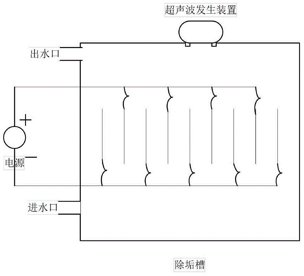
The invention relates to an external cold water descaling device for a direct-current converter valve cooling system and a method. The external cold water descaling device comprises a descaling tank, a direct-current power source, an electrode, an ultrasonic generator and a scale residue collection tank, a cathode and an anode of the electrode are corresponding connected with a cathode and an anode of the direct-current power source, the electrode is fixedly mounted in the descaling tank, the ultrasonic generator is mounted on the descaling tank, the scale residue collection tank is mounted at the bottom of the descaling tank, and the bottom of the descaling tank is open. The method includes: fixedly mounting the electrode with the descaling tank, and applying low voltage on the electrode; enabling calcium and magnesium ions of spraying water to be in chemical reaction at the cathode of the electrode to generate fouling; applying vibration of certain frequency on the electrode, and adjusting vibration frequency of the ultrasonic generator to vibration frequency identical when the fouling is adhered on the electrode to enable the fouling to shed into the scale residue collection tank. Through the descaling device and the method, scaling ions in spraying water can be removed, and the scaling problem of a cooling tower in a convertor station is solved.

Description

technical field [0001] The invention relates to a device and a method for a DC power transmission system, in particular to a device and method for descaling external cold water in a DC converter valve cooling system. Background technique [0002] The converter valve is the core equipment of the DC transmission project. By sequentially connecting the three-phase AC voltage to the DC terminal to obtain the desired DC voltage and realize power control, its value accounts for about 22-25% of the total price of the complete set of equipment in the converter station. . [0003] The design of the converter valve applies the latest technology and research results of power electronics technology, light-controlled conversion technology, high-voltage technology, control technology and pressure equalization technology, cooling technology, and high-voltage insulating materials. The main technical difficulty lies in: the converter valve temporarily The establishment of the state simulati...

Claims


Application Information

Patent Timeline
Patent Type & Authority Applications(China)
IPC IPC(8): C02F5/00C02F1/46C02F1/36
Inventor 汤广福王航周建辉查鲲鹏文玉良杨少军卢志敏
Owner STATE GRID CORP OF CHINA
Learn More