Anchoring structure for reinforcing T beam FRP

A technology of anchoring structure and FRP sheet, which is applied in the bridge and construction fields, can solve problems such as brittle failure of reinforcement devices, secondary damage of reinforced beams, secondary damage of reinforced beams, etc., to achieve easy assembly, good anchoring effect, and improve work efficiency Effect

Inactive Publication Date: 2016-06-29
SHENYANG JIANZHU UNIVERSITY
View PDF11 Cites 6 Cited by
  • Summary
  • Abstract
  • Description
  • Claims
  • Application Information

AI Technical Summary

Problems solved by technology

[0004] In addition, the above two methods not only have long construction period and complicated process, which will cause secondary damage to the reinforced beam, but also cause brittle failure of the reinforcement device, that is, if the screw filler does not fix the screw well, the anchor device may be damaged. Will be pulled out, resulting in peeling brittle failure together with the reinforcement material
And the screw needs to be deeply buried and multi-point anchored, because when the FRP is anchored, the nut is tightened and the stiffened screw will not be pulled out. The screw needs to be buried deeply. The deeper the screw is buried, the more serious the damage to the beam rib will be; The strip is narrow and the anchoring force is limited, so multi-point anchoring is required. If the anchoring device is installed at multiple points, it will cause secondary damage to the reinforced beam in many places, thus forming a vicious circle

Method used


Image

  • Anchoring structure for reinforcing T beam FRP
  • Anchoring structure for reinforcing T beam FRP
  • Anchoring structure for reinforcing T beam FRP

Examples


Embodiment 1

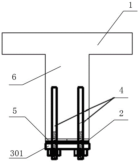
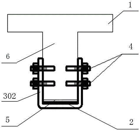
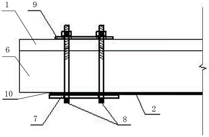
[0025] Such as image 3 , 4 , A kind of anchoring structure of the present invention that is used to strengthen T beam FRP shown in , 5, 6, comprises that the bottom of T beam beam rib 6 is provided with prestressed reinforcing material FRP sheet material 2, and its described FRP sheet material 2 lower end is provided with Pressing plate 7; there is also a carbon fiber cloth impregnated adhesive layer 10 belonging to A-grade epoxy resin glue between the FRP sheet 2 and the pressing plate 7. The pressing plate 7 is hooped by two U-shaped screws 8 with threads on the upper ends, and the The upper ends of the U-shaped screw rods 8 pass through the T-beam wing plate 1 and the upper edge top plate 9 respectively, and are fastened by spring washers and nuts. Both the pressure plate 7 and the upper edge top plate 9 are made of No. 45 steel plates, and the U-shaped screw 8 is made of R235 steel bars.

Embodiment 2

[0027] The present invention is an anchoring structure for reinforcing T-beam FRP, which comprises the reinforcement material FRP sheet 2 pasted on the bottom of the T-beam rib 6, and the lower end of the FRP sheet 2 is provided with a pressing plate 7; the FRP sheet 2 and the pressing plate 7 There is also an epoxy resin adhesive layer 10 between them, which is fastened by gaskets and bolts. The pressure plate 7 and the upper edge top plate 9 are all made of No. 20 steel plates. Others are the same as in Embodiment 1, and will not be repeated.

Embodiment 3

[0029] The present invention is an anchoring structure for reinforcing T-beam FRP, which includes reinforcing material FRP sheet 2 at the bottom of T-beam rib 6, and the pressure plate 7 and upper edge top plate 9 are all made of No. 20 steel plates. Others are the same as in Embodiment 1, and will not be repeated.


PUM


Abstract

The present invention relates to an anchoring structure, in particular to an anchoring structure for reinforcing T-beam FRP, which comprises a reinforcing material FRP sheet at the bottom of the T-beam rib, and a pressing plate at the lower end of the FRP sheet; The pressing plate is supported by at least two U-shaped screw rods with threaded upper ends, and the upper ends of the U-shaped screw rods pass through the T-beam wing plate and the upper edge top plate respectively, and are fastened by gaskets and nuts. The invention utilizes frictional resistance and cohesive force to achieve a good anchoring effect, which not only avoids secondary damage to the reinforced structure, but also does not cause brittle instant damage to the anchoring structure itself, and is simple and convenient in construction, and is not affected by seasons Features, high degree of industrialization, easy to popularize and use.

Description

technical field [0001] The invention relates to an anchoring structure, in particular to an anchoring structure for strengthening T-beam FRP, which belongs to the fields of buildings and bridges. Background technique [0002] In order to make the reinforced FRP sheet work together with the reinforced beam and prevent the FRP sheet from peeling off from the bottom of the beam during work, anchoring measures are generally applied to the FRP sheet. As we all know, the main stress-bearing part of the T-beam is the beam rib, and the wing plate is the roadway slab, which is the non-main stress-bearing part. Under the long-term load, the T-beam beam ribs will have cracks and large deflection, and the bearing capacity will decrease. Therefore, it is necessary to strengthen the beam ribs. The following methods are usually adopted in the prior art: [0003] The first method is to embed screw rods and narrow steel plates, such as figure 1 As shown, the second method is to anchor the...

Claims


Application Information

Patent Timeline
Patent Type & Authority Applications(China)
IPC IPC(8): E01D22/00E04G23/02
CPCE04G23/0218E04G2023/0262
Inventor 朱广山于玲汤伟孙宝芸洪媛于保阳
Owner SHENYANG JIANZHU UNIVERSITY
Why Eureka
Try Eureka