A Method of Using Projection Data to Remove Ring Artifacts Caused by CT Detector Faults

A technology of projection data and ring artifacts, which is applied in the field of medical image processing, can solve problems such as the inability to accurately estimate missing information, and the inability to well remove CT image ring artifacts, etc.

Active Publication Date: 2018-06-19
SOUTHERN MEDICAL UNIVERSITY
View PDF3 Cites 0 Cited by
  • Summary
  • Abstract
  • Description
  • Claims
  • Application Information

AI Technical Summary

Problems solved by technology

However, when the detection elements on the detector have continuous large-scale "necrosis", the above-mentioned master's degree thesis cannot accurately estimate the missing information by using only the interpolation method, not only cannot remove the ring artifact in the CT image well, And also new artifacts due to misestimation of missing information

Method used


Image

  • A Method of Using Projection Data to Remove Ring Artifacts Caused by CT Detector Faults
  • A Method of Using Projection Data to Remove Ring Artifacts Caused by CT Detector Faults
  • A Method of Using Projection Data to Remove Ring Artifacts Caused by CT Detector Faults

Examples


example 1

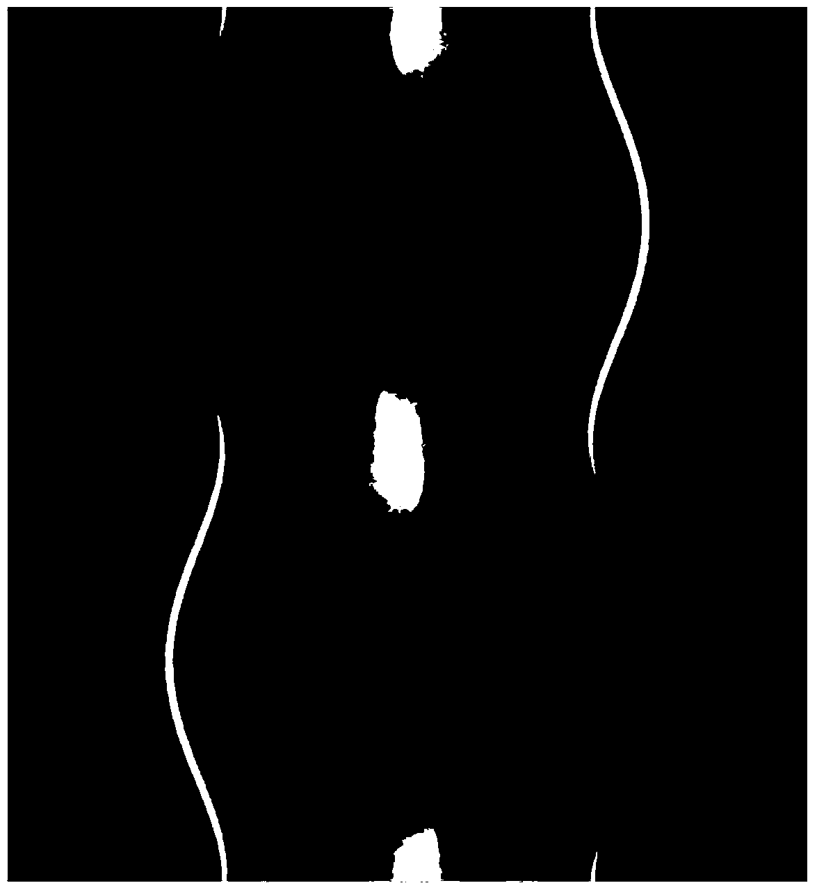
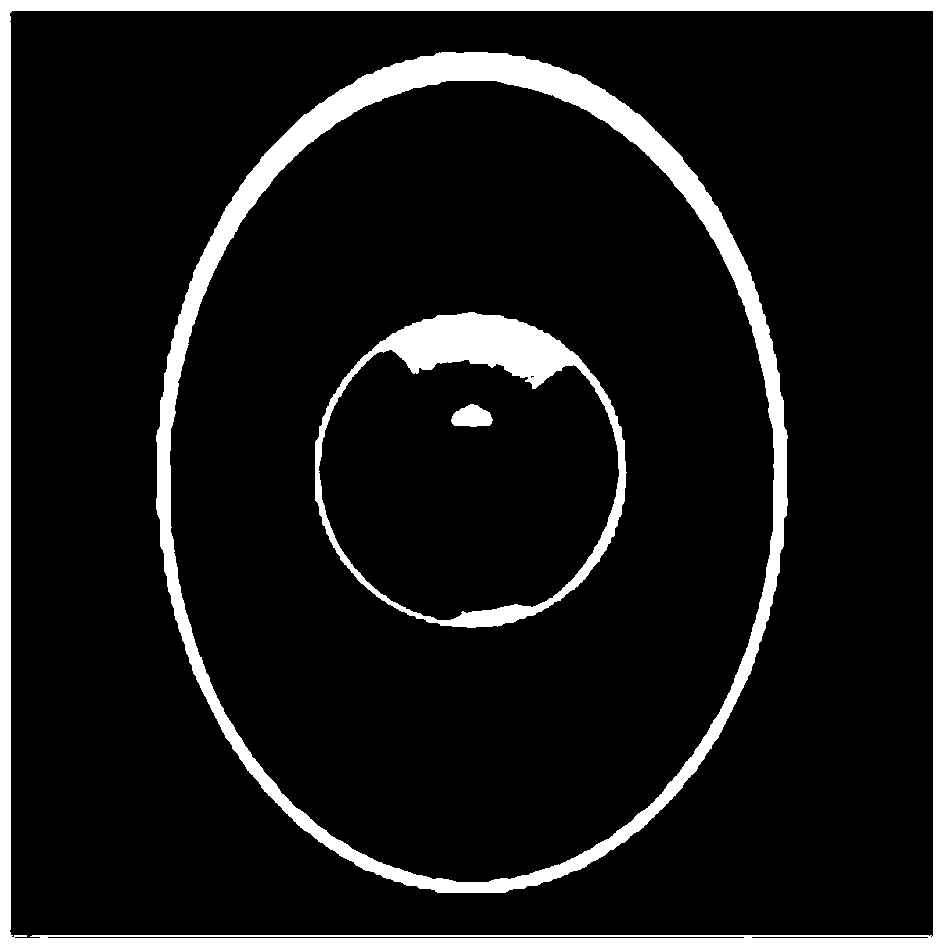
[0030] figure 1 The projected sinusoidal image of a human head with a size of 256×256 obtained for a faulty flat panel detector with 367 CT detection elements, wherein the number of consecutive faulty CT detection elements of the faulty flat panel detector is 21, and located at the Columns 120 to 140 (failure rate 21 / 367=5.7%). figure 1 The image shown is obtained in an orbital CT imaging system, wherein the distance from the focal point of the radiation source of the CT imaging system to the system rotation center is 500 mm, and the distance from the system rotation center to the detector is 500 mm. figure 1 The image shown is the projection data of 720 angles obtained by using the above-mentioned circular orbit CT imaging system to collect once at intervals of 0.5 degrees within a range of 360 degrees. The obtained projection data are directly reconstructed by filtered back projection to obtain the following figure 2 CT image shown. Depend on figure 2 It can be seen th...

example 2

[0053] In order to further verify the technical effect of the ring artifact removal method of the present invention, the inventor has also done the following research:

[0054] 1. Obtain a comparison image

[0055] (A) The projected sinusoidal matrices obtained in the 1st and 2nd iterations of step (5) of Example 1 are respectively subjected to filtered back-projection reconstruction, and the results are as follows Figure 5 shown in a and 5b.

[0056] (B) According to the same method as example 1, deal with it separately Image 6 a and Figure 7 The CT projection data corresponding to a, the reconstruction result is as follows Image 6 c and Figure 7 as shown in c. in, Image 6 a is the CT image obtained when the detectors in the 120th row to the 130th row have continuous failures (failure rate 11 / 367=3%), Figure 7 a is the CT image obtained when the detectors in the 80th row to the 180th row have continuous faults (failure rate 101 / 367=27.52%); Image 6 a and Fig...


PUM


Abstract

The invention relates to a method for removing annular artifacts caused by CT detection element faults by use of projection data. The method comprises the following steps: 1, introducing the projection data to obtain a matrix A, detecting a position of a fault area in the matrix A, and obtaining a matrix B by performing linear interpolation on a column corresponding to the fault area by use of two columns of data apart from the left column and the right column of the fault area; 2, after filtering back projection reconstruction is performed on the matrix B, then carrying out mean value filtering and forward projection, and obtaining a projection sine matrix C; 3, subtracting the matrix C from the matrix A, and then obtaining a matrix D by performing linear interpolation processing on the column corresponding to the fault area by use of the left column of data and the right column of data apart from the column corresponding to the fault area in a difference matrix; 4, obtaining a matrix E by adding the matrix C to the matrix D; and 5, returning to the second step, cycling the second step to the fourth step until preset iteration frequency is reached, and then obtaining a CT image after the artifacts are removed by performing the filtering back projection reconstruction on an obtained result. The method provided by the invention can eliminate the annular artifacts caused by continuous large-area faults of CT detection elements.

Description

technical field [0001] The invention relates to a medical image processing, in particular to image enhancement or restoration, in particular to a CT image ring artifact elimination method. Background technique [0002] CT, or computed tomography, is widely used in many fields such as medical diagnosis. However, in the CT system, due to the constraints of the processing precision and service life of the detector, the reconstructed CT image is often accompanied by the appearance of ring artifacts. Ring artifacts can affect subsequent image processing operations, such as image denoising, image segmentation, image measurement, and so on. [0003] CT image ring artifact correction methods are mainly divided into CT image correction method and projection sinogram correction method. The idea of ​​the CT image correction method is to firstly transform the circular artifact in the Cartesian coordinate system to the polar coordinate system, transform the shape of the artifact from a...

Claims


Application Information

Patent Timeline
Patent Type & Authority Patents(China)
IPC IPC(8): G06T5/00
CPCG06T5/002G06T2207/10081G06T2207/20182G06T2207/30004
Inventor 周凌宏齐宏亮袁翠云陈梓嘉徐圆吴书裕
Owner SOUTHERN MEDICAL UNIVERSITY
Why Eureka
Try Eureka