
Flexible control device and method for reactive compensation of distribution station area

A technology for distribution station area and control device, which is applied in reactive power compensation, circuit devices, reactive power adjustment/elimination/compensation, etc. Problems such as increased zero-sequence current and unbalance

Inactive Publication Date: 2016-06-29
XIAN HIRATE NET ELECTRIC EQUIP CO LTD
View PDF6 Cites 10 Cited by
  • Summary
  • Abstract
  • Description
  • Claims
  • Application Information

AI Technical Summary

Problems solved by technology

However, in recent years, with the development and progress of society, people often use a large number of heavy power single-phase and three-phase unbalanced electrical loads with unreasonable time-space distribution in daily life, resulting in increasingly serious asymmetry in the normal operation of the power distribution system in the station area. (Three-phase load imbalance) problem, resulting in increased loss of distribution transformers and lines, increased zero-sequence current of distribution transformers, resulting in local overheating of transformers, reduced operating safety of electrical equipment and reduced accuracy of electric energy measurement, etc.
Obviously, the above-mentioned known compensation control methods are only limited to compensation of reactive power in the distribution area, and cannot effectively solve the problem of unbalanced adjustment and compensation of three-phase loads, and have the defects of single function and poor flexibility

Method used


Image

  • Flexible control device and method for reactive compensation of distribution station area
  • Flexible control device and method for reactive compensation of distribution station area
  • Flexible control device and method for reactive compensation of distribution station area

Examples


Embodiment Construction

[0034] The content of the present invention will be further described below in conjunction with the accompanying drawings.

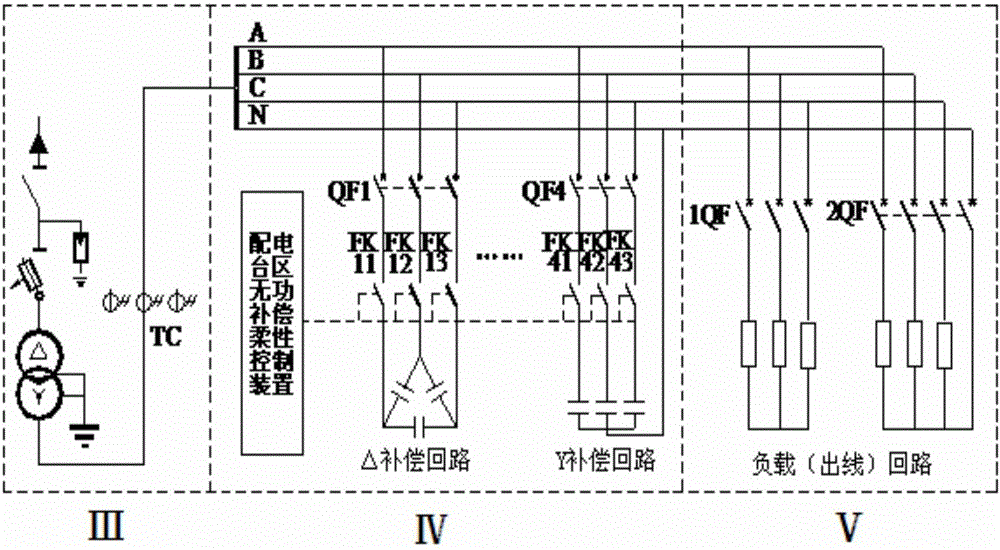
[0035] as attached figure 1 As shown, the distribution station area system adopts the three-phase four-wire power supply mode, including three-phase three-wire and three-phase four-wire loads, and the compensation circuit for unbalanced reactive power and three-phase loads is composed of the △ connection compensation circuit and the Y connection compensation circuit. composition.

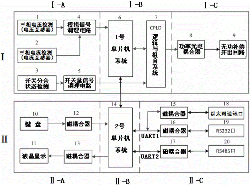
[0036] The structure of an embodiment of the flexible control device for reactive power compensation in the distribution station area of ​​the present invention is shown in the attached figure 2 As shown, it is composed of the operation control link I and the communication and human-computer interaction link II, and the data exchange is carried out between the two parts through the high-speed SPI bus.

[0037] The operation control link Ⅰ is composed of three parts: the ele...


PUM


Abstract

The invention relates to a flexible control device and method for reactive compensation of a distribution station area. The control device is composed of an operation control link that exchanges data by a high speed SPI bus and a communication and man-machine interaction link; and the control method provided by the invention comprises the steps of collecting a three-phase instantaneous voltage value and a current value of a distribution station area system to calculate and obtain active power, reactive power, a power factor and current unbalance degree, selecting a corresponding compensation control strategy according to the size of the current unbalance degree, converting a network combination structure of an existing active compensator capacitor bank to realize single reactive compensation or simultaneous reactive and three-phase load unbalance comprehensive compensation of the distribution station area. By adopting the flexible control device and method provided by the invention, the existing compensation network elements can be fully used, ''hardness is replaced by flexibility'', various load working conditions are applicable, the flexibility is good, the cost performance is good, and the single function defects of a conventional control device and method that only reactive compensation can be realized and that the three-phase load unbalance cannot be compensated.

Description

technical field [0001] The invention belongs to the field of flexible AC power distribution systems or electric power intelligent power distribution systems, and relates to a reactive power compensation flexible control device and a control method for distribution station areas. Background technique [0002] As the final link of power transmission and distribution in the power system, the distribution station area is an important part of the smart grid construction. Effective compensation and control of its reactive power can improve the utilization rate of the transformer in the distribution station area, reduce line voltage loss and active power loss, Enhance system operation safety and economy. [0003] Currently known in the art, reactive power compensation control strategies such as the power factor method, reactive current or reactive power method, and nine-zone diagram method are used to automatically switch parallel capacitor banks installed in the distribution stati...

Claims


Application Information

Patent Timeline
Patent Type & Authority Applications(China)
IPC IPC(8): H02J3/18H02J3/26
CPCY02E40/30Y02E40/50H02J3/1821H02J3/26
Inventor 赵怀军赵泽卿党喜玲张娜屈智锋
Owner XIAN HIRATE NET ELECTRIC EQUIP CO LTD
Learn More