Bi-directional puncture sheath
A sheath tube and sheath core technology, applied in the direction of puncture needles, puncture needles, catheters, etc., can solve the problems of blood vessel wall damage, neurovascular damage, difficult operation, etc., achieve good guiding effect, reduce blood vessel damage, reduce The effect of operational difficulty
- Summary
- Abstract
- Description
- Claims
- Application Information
AI Technical Summary
Problems solved by technology
Method used
Image
Examples
Embodiment 1
[0059] Embodiment 1 is a basic implementation of the present invention.
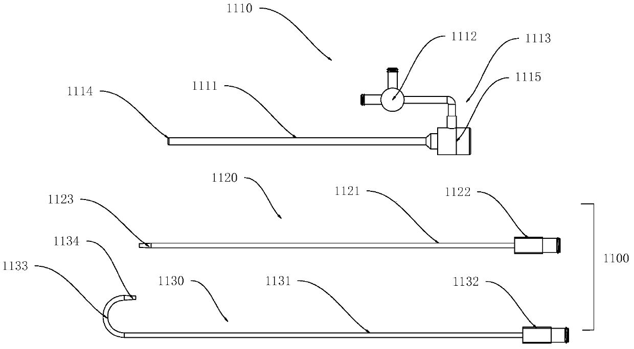
[0060] like Figure 1-7 As shown, a bidirectional puncture sheath includes a sheath tube assembly 1110 and a sheath core assembly 1100 for wearing a guide wire. The sheath core assembly 1100 includes at least one curved sheath core assembly 1130 and also includes one straight sheath core assembly 1120 .
[0061] like figure 1 , 12a As shown in -12d, the sheath tube assembly 1110 includes a sheath tube 1111 and a sheath tube attachment 1113. The sheath tube 1111 is a straight tube structure, and the sheath tube 1111 is provided with a sheath tube lumen 2116 through which the sheath tube lumen 2116 is provided. In this embodiment, the sheath tube lumen There is only one 2116, and it runs through both ends of the sheath tube 1111 in the axial direction. Curved, because the sheath lumen 2116 is used to accommodate the sheath core assembly 1100, and the sheath core assembly 1100 moves back and forth in th...
Embodiment 2
[0069] Example 2, such as Figure 8-20 As shown, in this embodiment, a bidirectional puncture sheath includes a sheath tube assembly 2110, a sheath core assembly for wearing a guide wire, and a sheath tube accessory. The sheath tube accessory includes a trifurcated joint 2130 and a Luer joint 2140 And the sheath tube adapter 2150.
[0070] like Figure 10 , 11 As shown, the sheath tube assembly 2110 includes a sheath tube 2114 , and the sheath tube 2114 includes a sheath tube distal end 2111 and a sheath tube proximal end 2112 , and the sheath tube proximal end 2112 is fixedly connected to a sheath tube joint 2150 .
[0071] like Figure 13 ,14 , 15a, and 15b, in this embodiment, the sheath core assembly is a curved sheath core assembly 2120, and the curved sheath core assembly 2120 includes a curved sheath core tube 2121, a sheath core head 2122 and a straight sheath core tube 2123, and the curved sheath core assembly 2120 The curved sheath core tube 2121 is bent, and the...
Embodiment 3
[0081] Example 3, such as Figure 21 As shown, two or more than two sheath tube assemblies 3110 are fixedly connected together and move along the inner lumen of the sheath tube at the same time. In this embodiment, the two sheath-core assemblies 3120 and 3120' can be fixed together, and the sheath-core assembly 3120 and the sheath-core assembly 3120' can advance and retreat together during operation, which simplifies the operation.
[0082] In this embodiment, the sheath tube 3111 is a layer of heat-shrinkable tube, which is used to fix the sheath-core assembly 3120 and the sheath-core assembly 3010 ′, so that the two sheath-core assemblies 3120 and the sheath-core assembly 3120 ′ can be pushed out from the introducer sheath 2500 at the same time . Wherein, the fixed position of the sheath tube 3111 starts from the bending position of the distal end of the sheath core assembly 3120, that is, the starting position 3126 of the bent sheath core tube. The material of the sheath t...
PUM
 Abstract
Description
Claims
Application Information
 - R&D
- Intellectual Property
- Life Sciences
- Materials
- Tech Scout
- Unparalleled Data Quality
- Higher Quality Content
- 60% Fewer Hallucinations
Browse by: Latest US Patents, China's latest patents, Technical Efficacy Thesaurus, Application Domain, Technology Topic, Popular Technical Reports.
© 2025 PatSnap. All rights reserved.Legal|Privacy policy|Modern Slavery Act Transparency Statement|Sitemap|About US| Contact US: help@patsnap.com


