Drying machine

A dryer and hollow shaft technology, applied in the direction of non-progressive dryers, dryers, drying solid materials, etc., can solve problems such as waste of energy, and achieve the effects of reducing energy consumption, high thermal efficiency, and a wide range of materials to be processed

Active Publication Date: 2016-07-06
NINGXIA G R FINE CHEM CO LTD
View PDF7 Cites 11 Cited by
  • Summary
  • Abstract
  • Description
  • Claims
  • Application Information

AI Technical Summary

Problems solved by technology

[0004] Existing hollow paddle dryers that use steam as the heat medium often contain steam when the steam is depleted of water, and the steam depletion water reaches 100

Method used


Image

  • Drying machine
  • Drying machine
  • Drying machine

Examples


Embodiment Construction

[0026] The present invention will be further described below in conjunction with the accompanying drawings and embodiments.

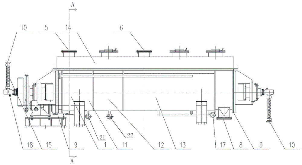
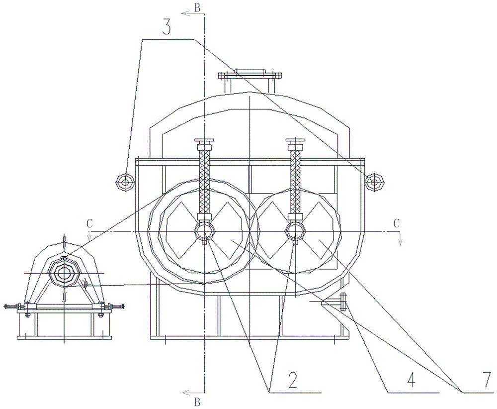
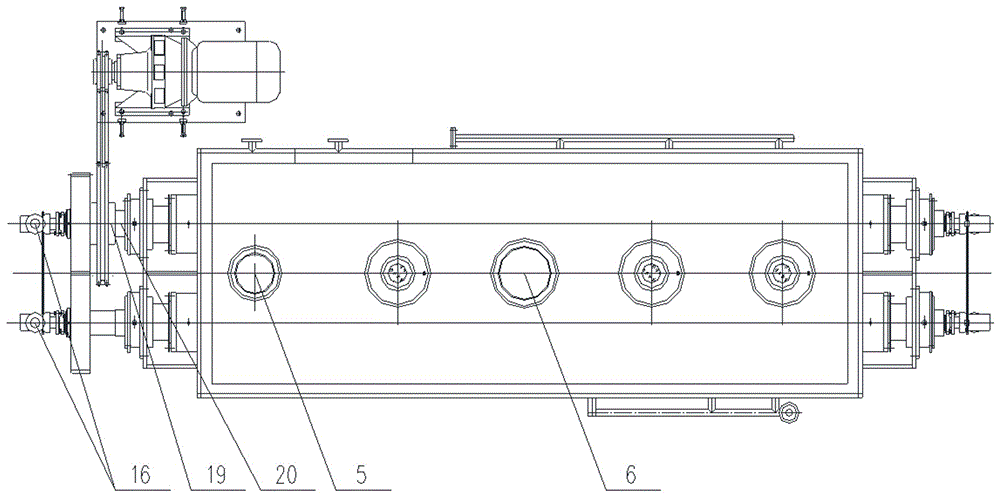
[0027] Such as figure 1 , figure 2 with image 3 As shown, the schematic diagrams of the front view, left view and top view of the dryer of the present invention are respectively provided. The dryer shown is composed of a housing 1, a hollow shaft 2, a steam inlet pipe 3, a hollow paddle 7, an end cover 9, The rotary joint 10, the heat carrier gas preheating section jacket 11, the steam condensate water preheating section jacket 12, the steam heating section jacket 13 and the driving device, the inside of the housing 1 shown is used for storing the material to be dried Cavity, the upper side of the front end of the housing 1 is provided with a material feeding port 5 communicating with the inner cavity, and an auger feeder can be connected above the material feeding port 5 to realize uniform feeding and feeding speed control. The lower side of the r...


PUM


Abstract

The invention relates to a drying machine. The drying machine comprises a shell, hollow shafts, rotating joints and driving devices, wherein the interior of the shell is a cavity for storing materials to be dried; a charging hole, a discharging hole and a hot carrier gas outlet are formed in the shell; and hollow blades are arranged on the hollow shafts. The drying machine is characterized in that three sections of jackets for preheating or heating the materials are arranged on the periphery of the shell; gas discharged by the hot carrier gas outlet is led into a hot carrier gas preheating section jacket; heat exchange fluid is led into a steam heating section jacket; and steam flashing discharged by the hollow shafts through the rotating joints and steam flashing discharged by the steam heating section jacket are led into a steam condensate preheating section jacket. The drying machine has the beneficial effects that the recycling of energy carried by waste heat and waste gas in a material drying process is realized by arranging the three sections of jackets; and the drying machine has the advantages of high heat efficiency, low energy consumption, small material loss and the like, reduces energy consumption and belongs to environmental friendly equipment.

Description

technical field [0001] The invention belongs to the technical field of drying equipment and relates to a hollow paddle dryer which can be used for drying materials in food, chemical, petrochemical, dye, industrial sludge and metallurgical industries. The drying machine of the present invention can be used for heating and drying of solid materials when a heat medium fluid medium such as steam, hot water, and heat transfer oil is introduced, and can be used for heating and liquefaction of a low-melting point solid material; It can be used for cooling of hot solid materials in brine. Background technique [0002] The dryer is a horizontal stirring continuous drying equipment mainly based on heat conduction. Because the stirring blade is shaped like a paddle, it is called a paddle dryer, and it is also called a trough dryer or a stirring dryer abroad. [0003] Because the heat required for equipment drying relies on indirect heating by heat conduction, the drying process does ...

Claims


Application Information

Patent Timeline
IPC IPC(8): F26B11/14F26B23/10F26B25/02F26B25/00
CPCF26B11/14F26B23/10F26B25/005F26B25/02F26B25/04Y02P70/10
Inventor 孙国庆李宏张卫民宋吉奎李涛陈桂元朱振峰
Owner NINGXIA G R FINE CHEM CO LTD
Why Eureka
Try Eureka