Redox flow battery system

A technology of liquid flow batteries and battery stacks, which is applied in the direction of fuel cells, fuel cell additives, fuel cell control, etc., and can solve problems such as inability to completely avoid electrolyte mixing, inconvenient maintenance, and complex device structures

Inactive Publication Date: 2016-07-06
SUZHOU JIURUN ENERGY TECH
View PDF5 Cites 7 Cited by
  • Summary
  • Abstract
  • Description
  • Claims
  • Application Information

AI Technical Summary

Problems solved by technology

However, in this type of method, the necessary device structure is relatively complicated, and various devices are intricately installed inside the storage tan...

Method used


Image

  • Redox flow battery system
  • Redox flow battery system

Examples


Embodiment 1

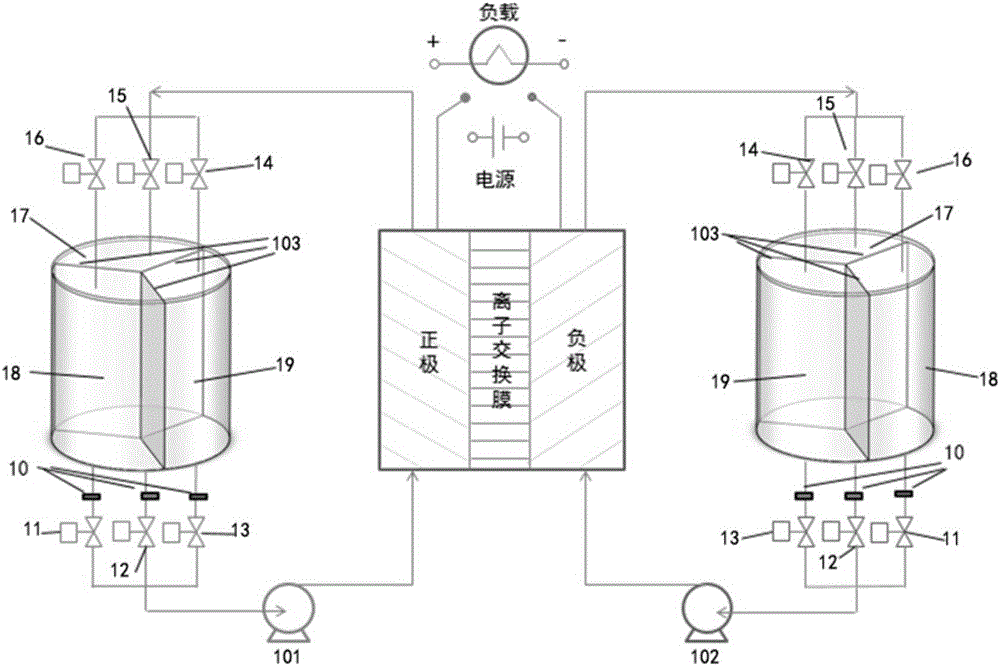
[0085] A flow battery system such as figure 1 As shown, the storage tank separator 103 is used to divide the positive electrode electrolyte storage tank into three cavities, which are respectively No. 1 cavity 17, No. 2 cavity 18, and No. 3 cavity 19. No. 1 and No. 3 cavity liquid inlet pipelines and cavity liquid outlet pipelines, and the No. 1 cavity liquid inlet valve (electric ball valve 15) and the No. Liquid valve (electric ball valve 16), No. 3 cavity liquid inlet valve (electric ball valve 14), No. 1 cavity liquid outlet valve (electric ball valve liquid valve (electric ball valve 11), No. 3 cavity liquid outlet valve (electric ball valve 13); end, as a branch of the main liquid outlet pipeline of the liquid flow circulation pipeline, the main liquid outlet pipeline is connected to the electrolyte outlet of the positive electrode; and the liquid outlet pipelines of No. 1, No. 2 and No. 3 cavities are connected in parallel It is arranged at the liquid outlet end of th...

Embodiment 2

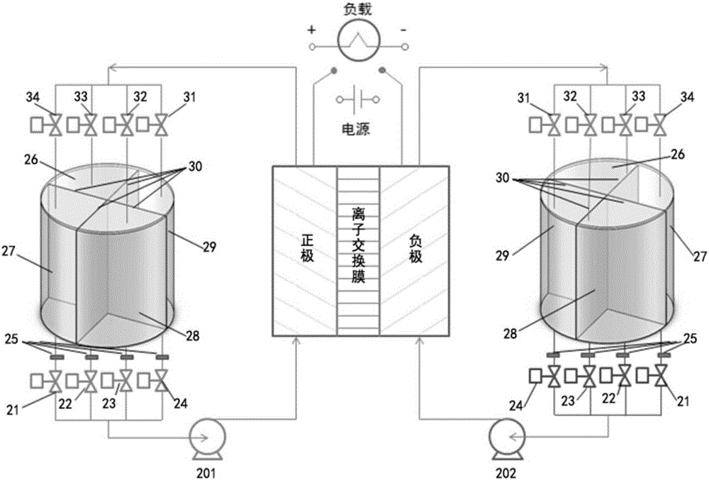
[0095] A flow battery system such as figure 2 As shown, the storage tank separator 30 is used to divide the positive electrode electrolyte storage tank etc. into four cavities, respectively No. 1 cavity 26, No. 2 cavity 27, No. 3 cavity 28, and No. 4 cavity 29. No. 1, No. 2, No. 3, and No. 4 cavity liquid inlet pipelines and cavity liquid outlet pipelines are connected, and the No. 1 cavity liquid inlet valve (electric Butterfly valve 33), No. 2 chamber liquid inlet valve (electric butterfly valve 34), No. 3 chamber liquid inlet valve (electric butterfly valve 32), No. 4 chamber liquid inlet valve (electric butterfly valve 31), liquid outlet in their respective chambers The pipeline is equipped with the liquid outlet valve of No. 1 chamber (electric butterfly valve 22), the liquid outlet valve of No. 2 chamber (electric butterfly valve 21), the liquid outlet valve of No. 3 chamber (electric butterfly valve 23), and the liquid outlet valve of No. 4 chamber (electric butterfly v...


PUM


Abstract

The invention provides a redox flow battery system. A positive electrolyte storage tank and/or a negative electrolyte storage tank of the redox flow battery system is partitioned into N and/or M cavities in a vertical direction, and the N and/or M cavities are arranged in a circumferential direction; during the running process and in each electrolyte storage tank, when a cavity liquid inlet valve of one of the cavities and a cavity liquid outlet valve of another cavity are opened, the other valves are closed, so that only two cavies are simultaneously communicated with a positive/negative liquid flow circulation pipeline all the time, and an electrolyte circulation loop is formed from a positive electrode/negative electrode of a battery stack; and moreover, an electrolyte is introduced to another empty cavity from a full cavity all the time, and thus, the electrolyte already flowing through the battery stack cannot be mixed with the electrolyte which does not flow through the battery stack. Therefore, by the redox flow battery system, the voltage efficiency can be improved, and the energy efficiency is further improved.

Description

technical field [0001] The invention relates to the field of chemical batteries, in particular to a liquid flow battery system. Background technique [0002] Electrochemical flow battery (electrochemical flow cell), referred to as flow battery, generally also known as redox flow battery (flowredoxcell or redoxflowcell) is a new type of large-scale electrochemical energy storage device. Liquid flow batteries have the following excellent characteristics: high efficiency, low cost, long life, fast response, excellent high current and rapid discharge capability, wide adaptable temperature range, good safety, no pollutant discharge, and large design scale Small, capable of buffering and storing the output of solar and wind energy, improving the output stability of solar and wind power, and showing great promise in the application of renewable energy such as wind energy and solar energy, and in large-scale energy storage systems such as peak shaving and valley filling. Great adva...

Claims


Application Information

Patent Timeline
IPC IPC(8): H01M8/18H01M8/04298H01M8/24
CPCH01M8/04298H01M8/18H01M8/184H01M8/249Y02E60/50
Inventor 刘京亮马志啟杨颖
Owner SUZHOU JIURUN ENERGY TECH
Why Eureka
Try Eureka