High-linearity stacked-structure radio frequency power amplifier

A radio frequency power, stacking structure technology, applied in high frequency amplifiers, power amplifiers, amplifiers, etc., can solve problems such as low output power and transistor breakdown, improve linearity, improve output voltage swing, and improve withstand voltage capability Effect

Inactive Publication Date: 2016-07-06
GUANGDONG UNIV OF TECH
View PDF4 Cites 1 Cited by
  • Summary
  • Abstract
  • Description
  • Claims
  • Application Information

AI Technical Summary

Problems solved by technology

As the power of the input signal increases, the output voltage signal also becomes larger, which will make the transistor on the uppermost layer of the structure the first to have a breakdown problem
In addition, since the output impedance of the two transistors in the cascode structure is not optimal impedance, the output power is small

Method used


Image

  • High-linearity stacked-structure radio frequency power amplifier

Examples


Embodiment Construction

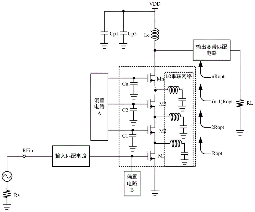
[0021] A preferred embodiment of the present invention, a radio frequency power amplifier with a high linearity stack structure, the radio frequency power amplifier includes an input matching circuit, an output broadband matching circuit, a bias circuit A, a bias circuit B, and at least two A power amplifying circuit in which the drains and sources of transistors are stacked together; wherein, the radio frequency signal source RFin is connected to the gate of the lowest transistor M1 of the power amplifying circuit through the input matching circuit, and the bias circuit B is connected to the gate of the transistor M1 at the bottom of the power amplifying circuit. The gate of the bottom transistor M1; the bias circuit A is connected to the gates of the other transistors of the power amplifier circuit except the bottom transistor, that is, transistors M2 to Mn; the source of the bottom transistor M1 Directly grounded, the gates of the remaining transistors are grounded by connec...


PUM


Abstract

The invention discloses a high-linearity stacked-structure radio frequency power amplifier. The high-linearity stacked-structure radio frequency power amplifier comprises an input matching circuit, an output broadband matching circuit, a bias circuit A, a bias circuit B, and a power amplification circuit at least formed by two connected and stacked transistor drains and sources, wherein a signal source is connected with a grid of a transistor at the bottom of the power amplification circuit through the input matching circuit, and the bias circuit B is also connected with the grid; the bias circuit A is connected with grids of other transistors of the power amplification circuit, the grids are grounded by connecting a grid capacitor, and sources are grounded by connecting LC series circuit; a drain of a transistor at the top of the power amplification circuit is connected with a load through the output broadband matching circuit. According to the circuit structure of the high-linearity stacked-structure radio frequency power amplifier, the linearity and voltage endurance capability of the radio frequency power amplifier are improved; besides, output voltage swing, operating bandwidth, power efficiency, power gain and maximum output power of the radio frequency power amplifier can be also improved, and a greater secondary harmonic suppression effect is also achieved.

Description

technical field [0001] The invention relates to a power amplifier, in particular to a radio frequency power amplifier. Background technique [0002] The RF power amplifier is an important part of the modern wireless communication system, which can amplify the power of the RF signal with very small power without distortion, and then radiate it through the antenna. [0003] As the functional modules of portable devices and the modulation methods of modern communication systems become more and more complex, for example, in order to meet the needs of different users, wireless mobile phones generally support two or more It is required that modern communication systems adopt modulation methods such as QPSK, which requires that power amplifiers used in new generation communication systems must have high power efficiency, linearity and bandwidth. [0004] In addition, as the functional modules of portable devices become more and more complex, integrating each functional module on o...

Claims


Application Information

Patent Timeline
Patent Type & Authority Applications(China)
IPC IPC(8): H03F1/02H03F1/32H03F3/19H03F3/21
CPCH03F1/0205H03F1/32H03F3/19H03F3/21
Inventor 林俊明章国豪张志浩余凯黄亮
Owner GUANGDONG UNIV OF TECH
Why Eureka
Try Eureka