Desulfurization and denitration integrated device

A desulfurization, denitrification and denitrification technology, which is applied in the direction of gas treatment, chemical instruments and methods, and the separation of dispersed particles, can solve the problems of uneven mixing of flue gas and reducing agent, low utilization rate of carbon-based catalysts, and uneven air distribution. Achieve high adsorption performance and reactivity, reduce investment and operating costs, and accelerate the denitrification rate

Active Publication Date: 2016-07-13
山西科瑞信环保工程有限公司
View PDF7 Cites 8 Cited by
  • Summary
  • Abstract
  • Description
  • Claims
  • Application Information

AI Technical Summary

Problems solved by technology

[0005] The purpose of the present invention is to solve the problem of low desulfurization and denitrification efficiency of the system caused by uneven airflow distribution, low utilization rate of carbon-based catalyst (activated carbon / activated coke), uneven mixing of flue gas and reducing agent, etc. during the flue gas purification process. Provides a desulfurization and denitrification integrated device with reasonable gas distribution, compact structure, high purification efficiency, wide application range and easy promotion

Method used


Image

  • Desulfurization and denitration integrated device
  • Desulfurization and denitration integrated device
  • Desulfurization and denitration integrated device

Examples


Embodiment 1

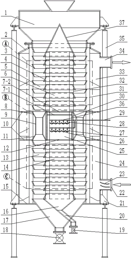
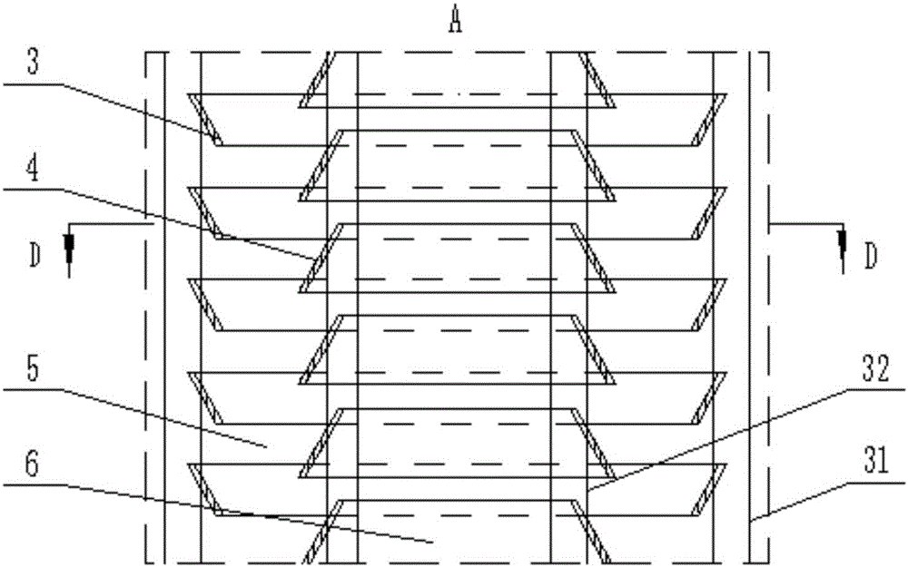
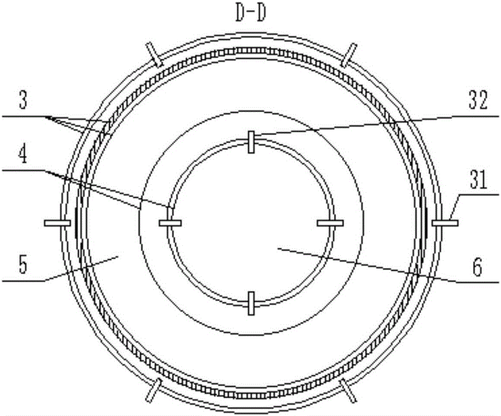
[0033]An integrated device for desulfurization and denitrification includes a top silo 1, a shell 2, an ammonia injection main pipe 29, a denitrification chamber 5, an air inlet 22, an exhaust port 34, a discharge valve 18, and a bracket 35. It is characterized in that the shell 2 The top of the tank is provided with a top silo 1, and the shell 2 is divided into three parts: the upper denitrification zone, the middle buffer zone and the lower desulfurization zone by the upper and lower annular partitions 10; chamber 5 and the denitrification air inlet chamber 6, the denitrification chamber 5 is composed of a plurality of inverted truncated hollow cones 3 and a plurality of truncated hollow cones 4, each inverted truncated hollow cone 3 is connected by an outer connecting rod 31, and each flat The truncated hollow cone 4 is connected by an inner connecting rod 32, the inverted truncated hollow cone 3 and the truncated hollow cone 4 are vertically staggered, the denitrification c...

Embodiment 2

[0049] The inclination angle of the inverted truncated hollow cone 7 is 120°, the interval between the adjacent inverted truncated hollow cones 7 is 78mm, and the inclination angle of the truncated hollow cones 9 is 60°, between the adjacent truncated hollow cones 9 The interval between them is 43mm, the vertical distance between the adjacent ammonia injection branch pipes 36 in the ammonia mixing cylinder wall 30 is 220mm, the horizontal distance between the adjacent nozzles 28 of the same ammonia injection layer is 100mm, and the rectangular hole of the equalizer plate 12 is 5*30mm, the aperture of the first rectifying plate 7-1 is 10mm, and the opening rate is 47.21%, the aperture of the second rectifying plate 7-2 is 8mm, and the opening rate is 50.91%, and the rest is the same as that of embodiment 1.

Embodiment 3

[0051] The inclination angle of the inverted truncated hollow cone 7 is 115 °, the interval between the adjacent inverted truncated hollow cones 7 is 63 mm, and the inclination angle of the truncated hollow cones 9 is 65 °, between the adjacent truncated hollow cones 9 The interval between them is 55mm, the vertical distance between the adjacent ammonia injection branch pipes 36 in the ammonia mixing cylinder wall 30 is 160mm, the horizontal distance between the adjacent nozzles 28 of the same ammonia injection layer is 75mm, and the rectangular hole of the equalizer plate 12 is 4*23mm, the aperture of the first rectifying plate 7-1 is 8mm, and the opening rate is 30.8%, the aperture of the second rectifying plate 7-2 is 6mm, and the opening rate is 37.4%, and the rest is the same as that of embodiment 1.


PUM


Abstract

A desulfurization and denitration integrated device comprises a top bin (1), a shell (2), an ammonia spraying master pipe (29), a denitration chamber (5), a smoke inlet (22), a smoke discharging port (34), a discharging valve (18) and a support (35), wherein the shell is divided into an upper denitration region, a middle buffering region and a lower desulfurization region through upper and lower annular partitioning plates (10), the denitration region and the desulfurization region are cut into different chambers through inverted truncated hollow cones (3) and truncated hollow cones (4), and a purified smoke outlet chamber (33), the denitration chamber (5) and a denitration smoke inlet chamber (6) are sequentially arranged in the denitration region from outside to inside; a desulfurization smoke inlet chamber (24), a desulfurization chamber (13) and a desulfurization smoke outlet chamber (14) are sequentially arranged inside the desulfurization region from outside to inside; the desulfurization chamber (13) and the denitration chamber (5) are communicated through discharging pipes (9) in the buffering reigon, and the desulfurization smoke outlet chamber (14) and the denitration smoke inlet chamber (6) are communicated through an eddy ammonia mixing chamber (25) in the buffering region.The occupied area is small, smoke flow is distributed reasonably, the quantity of filled purifying agent is small, and desulfurization and denitration efficiency is high.

Description

technical field [0001] The invention belongs to the purification technology of flue gas desulfurization and denitrification, and in particular relates to a desulfurization and denitrification integrated device. Background technique [0002] With the serious impact of environmental problems such as acid rain, smog, and photochemical smog on people's production and life in recent years, the emission control of SOx and NOx that cause these environmental problems has become a thorny issue. Therefore, it is very important to develop economical and efficient desulfurization and denitrification technologies. strategic significance. [0003] Existing desulfurization and denitrification technologies usually perform desulfurization and denitrification in two independent devices to avoid the poisoning effect of SOx in the flue gas on the denitrification catalyst, but the existence of two sets of independent removal devices results in long process flow and land occupation. Large area, ...

Claims


Application Information

Patent Timeline
Patent Type & Authority Applications(China)
IPC IPC(8): B01D53/90B01D53/56B01D53/50
CPCB01D53/8609B01D53/8631B01D53/90B01D2258/0283
Inventor 张智聪李巧艳曹伟郑玲云
Owner 山西科瑞信环保工程有限公司
Why Eureka
Try Eureka