Reflective laser differential confocal curvature radius measuring method and device

A differential confocal, radius of curvature technology, used in measuring devices, optical devices, instruments, etc., can solve problems such as harsh environmental conditions, shorten the length of guide rails, improve anti-environmental interference ability and system reliability, and improve measurement. The effect of speed and efficiency

Active Publication Date: 2016-07-13
BEIJING INSTITUTE OF TECHNOLOGYGY
View PDF5 Cites 10 Cited by
  • Summary
  • Abstract
  • Description
  • Claims
  • Application Information

AI Technical Summary

Problems solved by technology

Compared with the first type of measurement method, this type of measurement method has higher measurement accuracy and does not damage the surface of the mirror under test. However, since the interference fringes are seriously affected by environmental factors such as airflow, temperature, and vibration, extremely harsh environmental conditions are put forward. Require

Method used


Image

  • Reflective laser differential confocal curvature radius measuring method and device
  • Reflective laser differential confocal curvature radius measuring method and device
  • Reflective laser differential confocal curvature radius measuring method and device

Examples


Embodiment 1

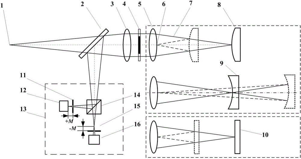
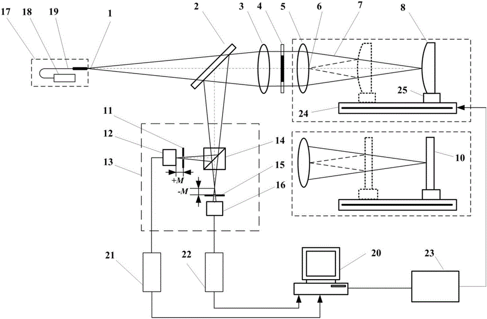
[0037] Such as figure 2 As shown, the embodiment of the present invention is based on figure 1 The schematic diagram of the reflective laser differential confocal radius of curvature measurement system shown can also include: point light source generating device 17, laser 18, optical fiber 19, main control computer 20, pre-focus detector image acquisition card 21, post-focus detection image acquisition card 22, electromechanical control device 23, linear translation guide rail 24, and adjustment frame 25; wherein, the point light source 1 can be composed of a laser 18 and an optical fiber 19; the differential confocal detection system 13 can be composed of a pre-focus light intensity detector 12, a focus Front pinhole 11, dichroic prism 14, back-focus pinhole 15 and back-focus light intensity detector 16 are formed;

[0038] Such as figure 2 As shown, the process of using the reflective laser differential confocal curvature radius measurement method to achieve high-precisi...

Embodiment 2

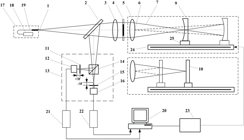
[0050] When measuring the measured concave mirror 9 with a curvature radius R≈-5000mm as an example, when the top focal length of the objective lens 5 is about 1045mm and the measurement aperture is 100mm, the reflective laser differential confocal curvature radius measurement device is as image 3 As shown, the measurement steps are:

[0051] Step 1. Place the measured concave mirror 9 in the measuring beam 7 behind the objective lens 5, and adjust the measured concave mirror 9 to be coaxial with the measuring beam 7;

[0052] Step 2, move the measured concave mirror 9 along the optical axis direction, when the measured concave mirror 9 is located near the focal point of the objective lens 5, move the measured concave mirror 9 to scan, and the image acquisition card 21 and the image acquisition card 22 collect the focal points respectively. The axial light intensity information of the front detector 12 and the back-focus detector 16 is differentially processed by the main con...


PUM


Abstract

The invention belongs to the technical field of precise optical measurement, and relates to a reflective laser differential confocal curvature radius measuring method and device.The method comprises the steps that by utilizing the characteristic that a laser differential confocal light intensity response curve zero crossing point precisely corresponds to a system focal point, focusing measurement is performed on the focal point of an objective lens and the vertex point of the back surface of the objective lens by moving a measured mirror to obtain a position difference value L1 of the measured mirror, then focusing measurement is performed on the focal point of the objective lens and the vertex point of the back surface of the objective lens by moving a reflecting mirror to obtain the position difference value L2 of the reflecting mirror, a curvature radius value of the measured mirror is solved through the measured position difference value L1 of the measured mirror and the measured position difference value L2 of the reflecting mirror, and high-precision measurement on the curvature radius is achieved.Compared with an existing measurement method, not only can curvature radius measurement on a concave mirror be achieved through the method, but also the method can be applied to curvature radius measurement on a convex mirror, and the method has the advantages of being high in measurement precision, short in measurement optical path, high in environment interference resisting capacity and the like.

Description

technical field [0001] The invention relates to a reflective laser differential confocal curvature radius measurement method and device, belonging to the technical field of precision measurement of optical element parameters. technical background [0002] Spherical optical elements are widely used in optical system research fields such as astronomical telescopic systems, high-resolution earth observation systems, and laser fusion systems. The radius of curvature is one of the most basic and important parameters of spherical optical elements, which directly affects the The performance and imaging quality of the system must be accurately tested. [0003] At present, in order to achieve high-precision measurement of the radius of curvature, researchers have proposed many different measurement methods, which can be mainly divided into the following two categories: [0004] The first category is the contact measurement method. This type of measurement method directly measures t...

Claims


Application Information

Patent Timeline
Patent Type & Authority Applications(China)
IPC IPC(8): G01B11/255
CPCG01B11/255
Inventor 赵维谦李志刚邱丽荣
Owner BEIJING INSTITUTE OF TECHNOLOGYGY
Why Eureka
Try Eureka