Method for measuring the cladding light ratio of double-clad fiber lasers

A technology of double-clad optical fiber and measurement method, which is applied in the direction of testing optical performance, etc., can solve the problems of limited measurement range, inability to detect the outer boundary of the cladding light field, blurred edges, etc., and achieves the effect of a large measurement range.

Active Publication Date: 2017-08-11
NAT UNIV OF DEFENSE TECH
View PDF7 Cites 0 Cited by
  • Summary
  • Abstract
  • Description
  • Claims
  • Application Information

AI Technical Summary

Problems solved by technology

At this time, the response of the detector to the cladding light field will be equivalent to the noise of the detector itself, which means that the detector cannot detect the cladding light field and the outer boundary of the cladding light field, that is, it cannot simultaneously detect the cladding light field and the fiber core light field imaging
On the other hand, since the core and the inner cladding of the double-clad fiber differ greatly in numerical aperture and cross-sectional area, it is impossible for the lens group to form a clear image of the core and the inner cladding at the same position (the aberration is less than 0.5 times the wavelength), that is, for the image of the core and the image of the inner cladding, there must be a blurred edge, which will lead to a decrease in the accuracy of the results of the detector test
Therefore although the patent document CN103616165A can realize the separation of the cladding light field and the fiber core light field under certain conditions, it can be used to test the loss of the optical fiber (core loss and inner cladding loss), but the measurement range of this method is severely limited Due to the dynamic response range of the detector and the accuracy is not ideal, it is not suitable for testing the cladding light ratio of the output light of high-power fiber lasers

Method used


Image

  • Method for measuring the cladding light ratio of double-clad fiber lasers
  • Method for measuring the cladding light ratio of double-clad fiber lasers
  • Method for measuring the cladding light ratio of double-clad fiber lasers

Examples


Embodiment 1

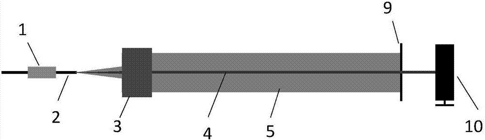
[0037] A method for measuring the cladding light ratio of a double-clad fiber laser of the present invention, such as figure 1 As shown, the method specifically includes the following steps:

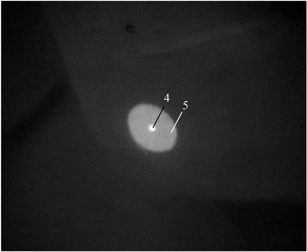
[0038] First, clamp the output fiber 2 of the double-clad fiber laser with the fiber holder 1, turn on the laser to emit light, adjust its output power to the level of watts, and adjust the position of the end face of the output fiber 2 so that it is located on the object plane of the lens group 3 . The lens group magnification that this embodiment adopts is 100 times, and object plane position is positioned at apart from lens group front surface 2cm place, image plane is positioned at apart from lens group rear surface 4m optical path place, the system aberration of lens group 3 to fiber core imaging is less than Or equal to 0.5 times the signal light wavelength. Further adjust the optical fiber holder 1, and repeatedly adjust the three-dimensional space position, pitch and swing of ...

Embodiment 2

[0042] In order to separate the core light, the cladding light of the signal light band, and the cladding light of the pump light band (ie, the remaining pump light) to obtain the ratio of the cladding light of the signal light band, Figure 4 The method for measuring the ratio of cladding light in the signal light band of the high-power double-clad fiber laser of the present invention is shown, comprising the following steps:

[0043] The lens group 3 used in this embodiment has a magnification of 100 times, the object plane is 2 cm from the front surface of the lens group 3, and the image plane is 4 m away from the rear surface of the lens group 3. First, clamp the output fiber 2 of the double-clad fiber laser with the fiber holder 1, turn on the laser to emit light, adjust its output power to the level of watts, and adjust the position of the end face of the output fiber 2 so that it is located on the object plane of the lens group 3 . The optical fiber holder 1 is further...

Embodiment 3

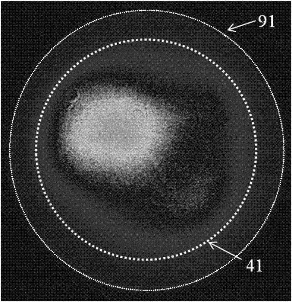
[0048] Figure 5 For adopting the method of the embodiment of the present invention 2 ( Figure 4 As shown in the principle), the test results of the cladding light ratio of the output optical signal light band of the high-power fiber laser show that the diameter of the core / cladding of the output fiber 2 is 20 / 400 μm, and the numerical aperture is 0.06 / 0.46 respectively. The abscissa is the pump power of the amplifier, the left ordinate is the ratio of cladding light in the signal light band to the signal light band of the output light, and the right ordinate represents the total output power (ie P 1 ). The black square curve represents the change of the total output power with the pump spectrum power of the amplifier, and the hollow diamond curve represents the cladding optical power P of the remaining pump light band 4 Variation with pump spectral power. Figure 5 The test results using different diaphragm apertures and the estimated results using cladding light filters ...


PUM


Abstract

The invention discloses a method for measuring a cladding light proportion of a double-clad fiber laser. The method comprises: performing equal-ratio amplification imaging on the end face of the output fiber of the double-clad fiber laser by using a lens group; disposing a diaphragm with an adjustable aperture diameter on the image surface of the lens group; enabling the fiber core light in the output light of the double-clad fiber laser to pass through the diaphragm but enabling the cladding light in the output light of the double-clad fiber laser to be blocked by the diaphragm by adjusting the aperture diameter of the diaphragm; testing the power P1 of output light spot in front of the diaphragm and the power P2 of fiber core light spot behind the diaphragm to obtain the proportion of the cladding light of the output light of the double-clad fiber laser as (P1-P2) / P1. The method is large in measurement range, high in measurement precision, and can be used for measuring the cladding light proportion of a high-power double-clad fiber laser.

Description

technical field [0001] The invention belongs to the field of fiber lasers, and relates to a method for measuring the cladding light ratio of a double-clad fiber laser, in particular to a measuring method for testing the cladding light ratio of a high-power fiber laser. Background technique [0002] Fiber lasers have obvious advantages in beam quality, volume, weight, efficiency, heat dissipation, etc., and have become one of the most popular research directions in the field of lasers. Single-clad gain fibers were often used in early fiber lasers. The characteristic of this fiber is that both the pump light and the signal light are transmitted in the fiber core. Since the diameter and numerical aperture of the fiber core are small, this makes the pump injected into the gain fiber The total power of the pump light is limited, which restricts the power increase of the fiber laser. The structure of the double-clad gain fiber includes a core, an inner cladding and an outer cladd...

Claims


Application Information

Patent Timeline
Patent Type & Authority Patents(China)
IPC IPC(8): G01M11/02
CPCG01M11/02
Inventor 孔令超冷进勇郭少锋周朴许晓军姜宗福陈金宝
Owner NAT UNIV OF DEFENSE TECH
Why Eureka
Try Eureka