A thermal fatigue testing machine

A testing machine and thermal fatigue technology, applied in the direction of instruments, measuring devices, scientific instruments, etc., can solve the problems of uneven heating, inaccurate experimental results, uneven cooling of samples, etc., and achieve low sample requirements and high experimental efficiency , The effect of high equipment utilization

Active Publication Date: 2019-03-29
JIANGSU UNIV OF SCI & TECH
View PDF12 Cites 0 Cited by
  • Summary
  • Abstract
  • Description
  • Claims
  • Application Information

AI Technical Summary

Problems solved by technology

[0004] Purpose of the invention: In order to overcome the deficiencies in the prior art, the present invention provides a thermal fatigue testing machine, the sample holder can rotate at a certain speed, which solves the problem of uneven heating of the sample during the thermal fatigue test. The problem of inaccurate results optimizes the effect of thermal fatigue samples and also solves the problem of uneven cooling of samples in the water tank

Method used


Image

  • A thermal fatigue testing machine
  • A thermal fatigue testing machine
  • A thermal fatigue testing machine

Examples


Embodiment Construction

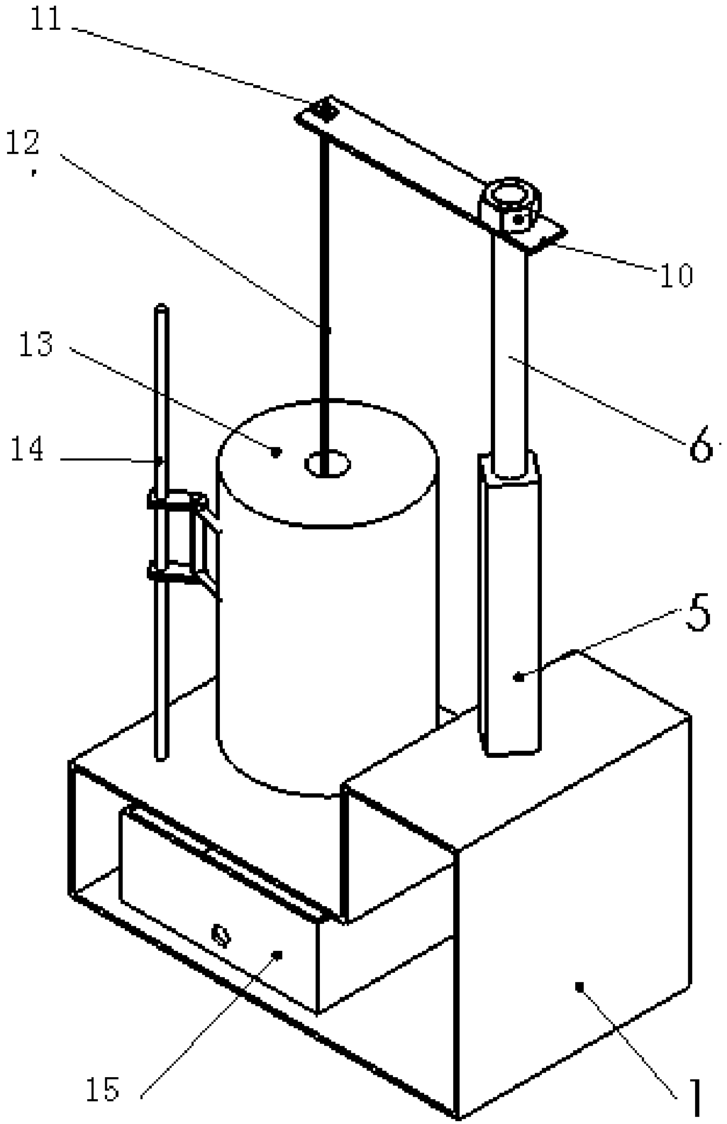
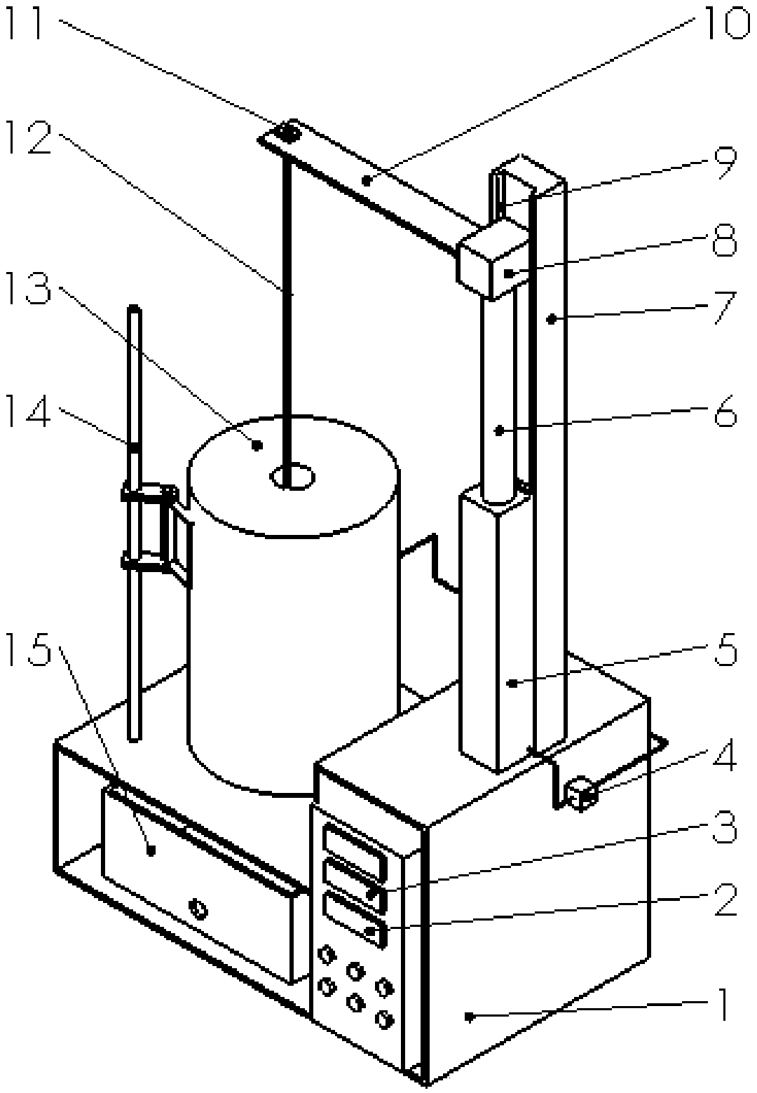
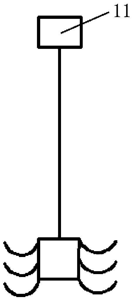
[0027] Such as Figure 1 to Figure 7 As shown, a kind of thermal fatigue testing machine of the present invention comprises workbench 1, heating system, cooling system, lifting system, control system and support 14, and described heating system comprises resistance heating furnace 13 and is positioned at resistance heating furnace 13 Thermocouple, the cooling system includes cooling water, a water tank 15 and a thermometer located in the water tank 15, the heating system is located on the workbench 1, the cooling system is located below the heating system, and the lifting system includes The cylinder 5, the piston rod 6 connected with the cylinder 5 and the support plate 10 positioned at the end of the piston rod 6, the end of the support plate 10 is fixedly equipped with a sample holder 12, which is connected with a motor 11 on the sample holder 12, The motor 11 is fixed on the support plate 10, the sample holder 12 is connected with the sample, and the sample is located in t...


PUM


Abstract

The invention discloses a thermal fatigue testing machine, which includes a workbench, a heating system, a cooling system, a lifting system, a control system and a support. The heating system includes a resistance heating furnace and a thermocouple, and the cooling system includes cooling water and a water tank. and a thermometer located in the water tank, the heating system is located on the workbench, the cooling system is located below the heating system, the lifting system includes a cylinder fixed on the workbench, a piston rod connected with the cylinder and a A support plate, the end of the support plate is fixedly equipped with a sample fixture, the sample fixture is connected with a motor, the motor is fixed on the support plate, the sample fixture is connected with the sample, and the sample is located in a resistance heating furnace. The sample fixture of the present invention can rotate by itself at a certain speed, which well solves the problem of inaccurate test results caused by uneven heating of the sample during the thermal fatigue experiment, optimizes the effect of the thermal fatigue sample, and also solves the problem of the sample being in the thermal fatigue test. Problem with uneven cooling in the sink.

Description

technical field [0001] The invention relates to a thermal fatigue testing machine, which belongs to the technical field of material testing. Background technique [0002] my country's research work on metal thermal fatigue began in the late 1950s. Due to the urgent need for the development and imitation of aviation materials, in 1958, the Beijing Institute of Aeronautical Materials designed and manufactured my country's first aircraft under the guidance of Soviet experts, referring to the "New Method for Thermal Fatigue Test of Heat-resistant Alloy Plates" of the former Soviet Aeronautical Materials Research Institute. Thermal fatigue testing machine - thermal fatigue testing machine for sheet metal. In 1962, the "thermal fatigue test method for metal and alloy plates" (draft) was formulated. In 1963, the method was revised and renamed "metal plate thermal fatigue test method", which was promoted and used as the standard of the Institute of Aeronautical Materials. In 1992, ...

Claims


Application Information

Patent Timeline
Patent Type & Authority Patents(China)
IPC IPC(8): G01N3/60
CPCG01N3/60
Inventor 许祥平周怡夏春智邹家生
Owner JIANGSU UNIV OF SCI & TECH
Why Eureka
Try Eureka