
Fundus optical full-field microangiography imaging device and method

An angiographic imaging and microvascular technology, applied in fundoscopy, medical science, blood flow measurement, etc., can solve the problems of high sampling speed, low spatial resolution, human body damage, etc.

Active Publication Date: 2016-07-20
佛山市灵觉科技有限公司
View PDF8 Cites 13 Cited by
  • Summary
  • Abstract
  • Description
  • Claims
  • Application Information

AI Technical Summary

Problems solved by technology

The laser Doppler frequency shift method has achieved skin burn repair and finger blood perfusion detection, but in this method, the speckle Doppler frequency shifted photons are captured by a high-speed area array camera, which requires a higher sampling speed, thus reducing Pixel resolution, so the spatial resolution is lower
The laser speckle contrast imaging method takes the contrast value as the imaging parameter, and has realized the microangiography imaging of living skin, cerebral cortex and other tissues, which can be used as a means of retinal imaging, but its theory is based on the temporal and spatial autocorrelation characteristics of speckle , in a certain environment, the speckle contrast is inversely proportional to the square root of the blood flow velocity, its ability to suppress background noise is not strong, and the imaging quality needs to be improved
At the same time, the above-mentioned method uses laser as the light source. When it is applied to fundus imaging, the laser needs to be used to directly irradiate the retina. Therefore, the requirements for laser power are very strict. If the power is too high, it may cause damage to the human body; if the power is too small, the imaging quality will be lost.

Method used


Image

  • Fundus optical full-field microangiography imaging device and method
  • Fundus optical full-field microangiography imaging device and method
  • Fundus optical full-field microangiography imaging device and method

Examples


Embodiment Construction

[0039] The preferred embodiments of the present invention will be described below in conjunction with the accompanying drawings. It should be understood that the preferred embodiments described here are only used to illustrate and explain the present invention, and are not intended to limit the present invention.

[0040] In the present invention, laser light is used as a light source, and the modulation depth is used as an imaging parameter, so that fundus optical full-field microangiography imaging with relatively high spatial resolution can be realized. In order to make the present invention clearer, the present invention will be further described in detail below with reference to the accompanying drawings and examples.

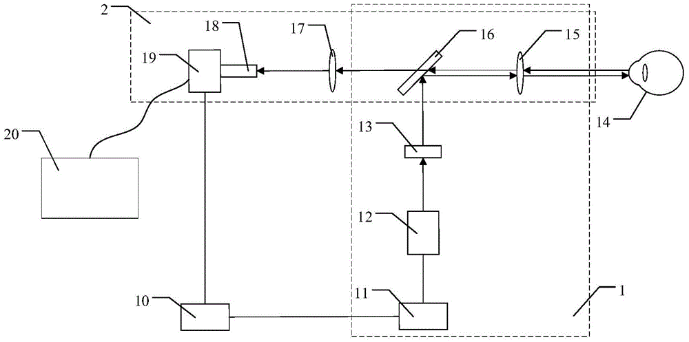
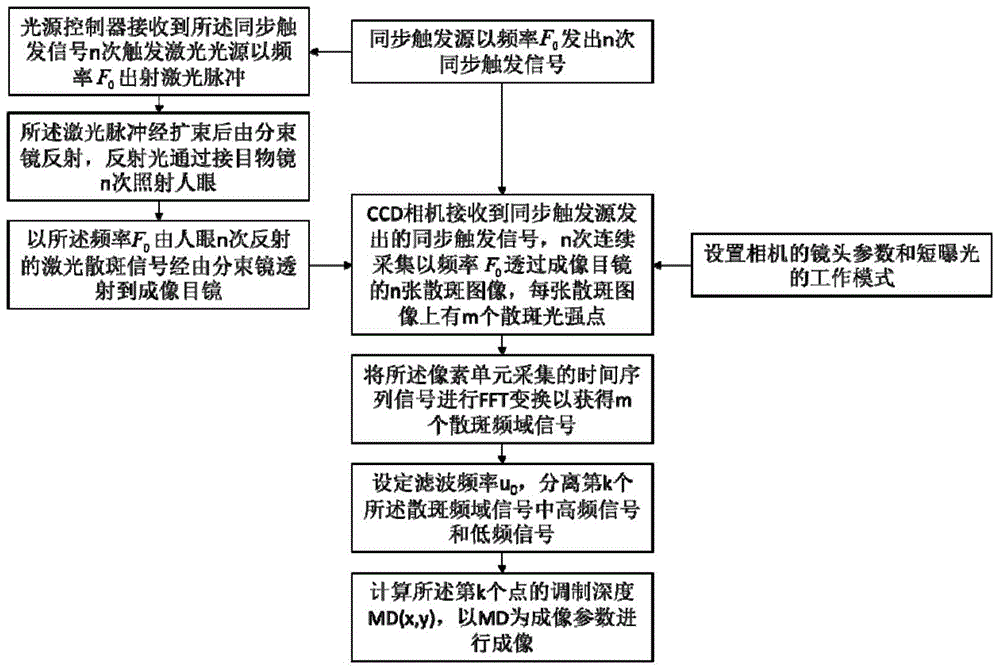
[0041] The invention provides an optical fundus full-field microangiography imaging device and method, which can realize full-field microangiography imaging with relatively high spatial resolution by using modulation depth as an imaging parameter. This emb...


PUM


Abstract

The invention relates to a fundus optical full-field microangiography imaging device and method. The device comprises a fundus illumination optical path, a fundus imaging optical path, a synchronous triggering source and a data processing system, wherein the fundus illumination optical path and the fundus imaging optical path are synchronously triggered by the synchronous triggering source; the fundus illumination optical path comprises a light source controller, a laser light source, a beam expanding lens, a beam splitter lens and an eye piece objective lens which are sequentially connected; and the fundus imaging optical path comprises an eye piece objective lens, a beam splitter lens, an imaging ocular lens, a lens and a COMS (Complementary Metal Oxide Semiconductor) camera which are sequentially connected. The device and the method have the advantages that the light source gives out laser at the same frequency as the sampling frame rate of the camera; the realization of the fundus microvessel imaging is ensured; and meanwhile, the laser power is reduced, so that the value reaches the range capable of being borne by human eyes. The method and the device can realize the fundus optical full-field microangiography imaging. The method has the advantages that a contrast agent is not needed; the resolution ratio, the signal-to-noise ratio and the detection depth are high; and the fundus blood capillary can be rebuilt.

Description

technical field [0001] The invention relates to the technical field of angiographic imaging, in particular to an optical full-field microangiographic imaging device and method for fundus. Background technique [0002] Blood flow imaging plays an important role in medical clinical diagnosis and basic pathological research. Microangiopathy is one of the most common complications associated with diabetes. It can cause lesions in multiple organs, including diabetic nephropathy, diabetes neurological disorders and diabetic retinopathy. In clinical medicine, the diagnosis of diabetic retinal microangiopathy is usually achieved by fundus fluorescein angiography, which requires the injection of sodium fluorescein optical contrast agent into the patient's eyes, which may cause adverse reactions in the human body. [0003] Full-field microangiography imaging using the principle of laser speckle is currently a research hotspot around the world, including methods such as laser Doppler ...

Claims


Application Information

Patent Timeline
IPC IPC(8): A61B3/12A61B5/026A61B5/00
CPCA61B3/1241A61B5/0071A61B5/026A61B3/10
Inventor 曾亚光张富丽韩定安
Owner 佛山市灵觉科技有限公司
Learn More