
Flow battery

A liquid flow battery and liquid flow hole technology, which is applied in the direction of fuel cells, regenerative fuel cells, fuel cell components, etc., can solve the problem of large electrode polarization, reduce the overall electrode polarization, and reduce the reaction activation polarization , to reduce the effect of ohmic polarization

Active Publication Date: 2016-07-27
DONGFANG ELECTRIC (CHENGDU) HYDROGEN FUEL CELL TECH CO LTD
View PDF4 Cites 11 Cited by
  • Summary
  • Abstract
  • Description
  • Claims
  • Application Information

AI Technical Summary

Problems solved by technology

[0003] The main purpose of the present invention is to provide a flow battery to solve the problem of excessive electrode polarization in the flow battery in the prior art

Method used

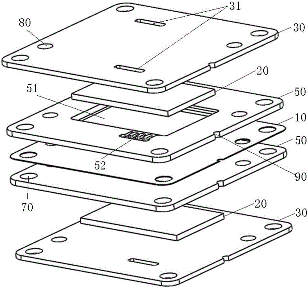
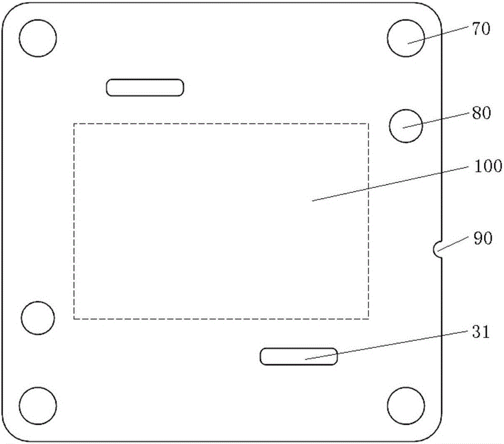
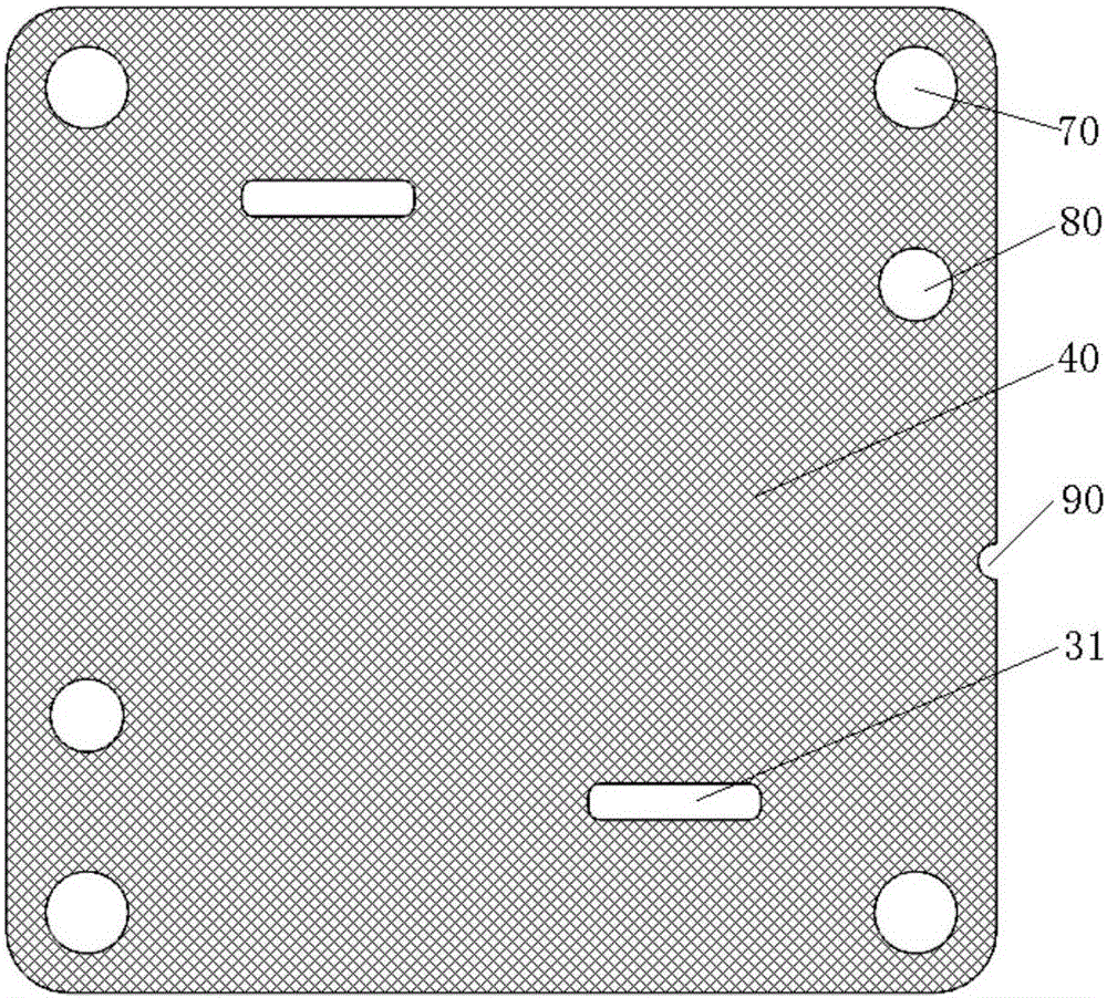

Image

  • Flow battery
  • Flow battery
  • Flow battery

Examples


Embodiment Construction

[0025] It should be noted that, in the case of no conflict, the embodiments in the present application and the features in the embodiments can be combined with each other. The present invention will be described in detail below with reference to the accompanying drawings and examples.

[0026] It should be pointed out that the following detailed description is exemplary and intended to provide further explanation to the present application. Unless defined otherwise, all technical and scientific terms used herein have the same meaning as commonly understood by one of ordinary skill in the art to which this application belongs.

[0027] In the present invention, in the absence of a contrary statement, the used orientation words such as "up and down" usually refer to the direction shown in the drawings, or refer to the vertical, vertical or gravity direction Similarly, for ease of understanding and description, "inside and outside" refer to inside and outside relative to the out...


PUM

PropertyMeasurementUnit
Surface roughnessaaaaaaaaaa

Abstract

The invention provides a flow battery. The flow battery comprises an ion exchange membrane, a plurality of electrodes and at least two current collection plates, wherein one electrode is arranged on each of the two sides of the ion exchange membrane, the at least two current collection plates are clamped between the electrodes and the two sides of the ion exchange membrane, a processing region is arranged on a surface, facing one side of each electrode, of each of the current collection plate, at least one part of the processing region is in contact reaction with the electrodes, and the surface roughness of the processing region is greater than or equal to 6.4 micrometers but smaller than or equal to 50 micrometers. By the flow battery, the problem of excessive high electrode polarization of the flow battery in the prior art is solved.

Description

technical field [0001] The invention relates to the field of batteries, in particular to a liquid flow battery. Background technique [0002] The surface of the current collector plate of the existing flow battery in contact with the electrodes is too smooth, which increases the electrode polarization of the flow battery, thereby reducing the output voltage of the flow battery; and after the integrated assembly of the flow battery , The current collector plate of the flow battery cannot provide enough static friction for the electrodes, so that the position of the electrode relative to the current collector plate is prone to change, affecting the stability of the battery, thereby reducing the overall performance of the flow battery. Contents of the invention [0003] The main purpose of the present invention is to provide a flow battery to solve the problem of excessive electrode polarization in the flow battery in the prior art. [0004] In order to achieve the above obj...

Claims


Application Information

Patent Timeline
IPC IPC(8): H01M8/18H01M8/02H01M8/0258
CPCH01M8/0258H01M8/18Y02E60/50
Inventor 刘佳燚周正李扬宋彦斌高艳刘红丽卢毅
Owner DONGFANG ELECTRIC (CHENGDU) HYDROGEN FUEL CELL TECH CO LTD
Learn More