Tracking method of rotor position of salient pole permanent magnet synchronous motor in motion state

A permanent magnet synchronous motor and rotor position technology, applied in the direction of control of electromechanical transmission, control of generator, motor generator control, etc., can solve the problems of unstable performance, increase of control interface and wiring, and the sensor is easily affected by the environment, etc.

Inactive Publication Date: 2016-07-27
SHANGHAI DAJUN TECH
View PDF2 Cites 19 Cited by
  • Summary
  • Abstract
  • Description
  • Claims
  • Application Information

AI Technical Summary

Problems solved by technology

[0002] The traditional methods of detecting motor speed and rotor position mostly use mechanical sensors such as photoelectric encoders or resolvers installed on the rotor shaft. High-precision and high-response speed and position sensors are expensive; concentricity problems may occur when mechanical sensors are installed. There is a deviation from the actual rotor position. The use of mechanical sensors increases the control interface and wiring of the system. When encountering interference or failure, the motor cannot be driven normally, which reduces the reliability of the system. The sensor is easily affected by the environment, and its performance in harsh environments unstable
[0003] When using speed sensorless control, since many control schemes mainly use the back electromotive force generated when the motor rotates to perform calculations, the amplitude of the back electromotive force is also zero at zero speed and cannot be measured; in addition, based on the back electromotive force of the motor The accuracy of the method depends on the parameters of the motor itself and the accuracy of flux observation and control, anti-interference ability and robustness (robust is the transliteration of Robust, the original meaning is robust and strong, here refers to the control system in abnormal and ability to survive in hazardous situations) is poor

Method used


Image

  • Tracking method of rotor position of salient pole permanent magnet synchronous motor in motion state
  • Tracking method of rotor position of salient pole permanent magnet synchronous motor in motion state
  • Tracking method of rotor position of salient pole permanent magnet synchronous motor in motion state

Examples


Embodiment 1

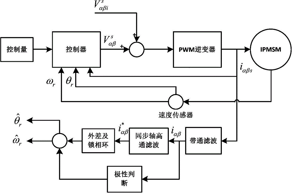
[0065] A method for tracking the rotor position of a salient pole permanent magnet synchronous motor in motion. The motor adopts a double-loop control based on a speed loop and a current loop, and is implemented according to the following steps:

[0066] a. Input the given control quantity into the controller, and the rotor angular velocity ω obtained by the motor through the mechanical sensor r and stator current i αβs For comparison, after PI adjustment, the control voltage in the rotating reference coordinate system is obtained, and then according to the rotor angle θ obtained from the sensor r Perform transformation to obtain the control voltage of the motor in the stationary two-phase coordinate system

[0067] b. Based on the two-phase model of the motor, the rotating high-frequency voltage signal injected on the motor winding and the control voltage of the motor After superposition, input the PWM inverter to control the three-phase bridge arm to drive the motor; ...


PUM


Abstract

The invention relates to the device field of controlling the synchronous motor, to be specific, relates to a tracking method of a rotor position of a salient pole permanent magnet synchronous motor in a motion state. The tracking method is characterized in that a, comparison is carried out; b, input of a PWM inverter is carried out; c, current i alfa beta of an alfa beta axis can be acquired; d, a current signal i alfa beta comprising the rotor position information can be acquired; e, whether the polarity of the estimated rotor position is identical to the polarity of the actual position can be determined, when the polarities are opposite, the compensation is required; f, after the current i afla beta is transmitted to the phase-locked loop, the estimated rotor angular speed omega r and the estimated rotor position theta r can be acquired by combining with the polarity determining module. The tracking method has advantages of high accuracy, strong applicability, safety, and reliability.

Description

technical field [0001] The invention relates to the field of devices for controlling synchronous motors, in particular to a method for tracking the rotor position of a salient pole permanent magnet synchronous motor in motion. Background technique [0002] The traditional methods of detecting motor speed and rotor position mostly use mechanical sensors such as photoelectric encoders or resolvers installed on the rotor shaft. High-precision and high-response speed and position sensors are expensive; concentricity problems may occur when mechanical sensors are installed. There is a deviation from the actual rotor position. The use of mechanical sensors increases the control interface and wiring of the system. When encountering interference or failure, the motor cannot be driven normally, which reduces the reliability of the system. The sensor is easily affected by the environment, and its performance in harsh environments unstable. [0003] When using speed sensorless control...

Claims


Application Information

Patent Timeline
Patent Type & Authority Applications(China)
IPC IPC(8): H02P21/14
Inventor 潘河清赵洪涛万茂文徐性怡
Owner SHANGHAI DAJUN TECH
Why Eureka
Try Eureka