

Method and device for double-stage expansion refrigeration high methane gas liquefaction
A two-stage expansion and methane gas technology, applied in the field of natural gas, can solve the problems of loss of expansion work, difficulty in separating heavy hydrocarbons, and large methane loss, and achieve the effects of small methane loss, reduced energy consumption, and high nitrogen separation coefficient
- Summary
- Abstract
- Description
- Claims
- Application Information
AI Technical Summary
Problems solved by technology
Method used
Image

Examples
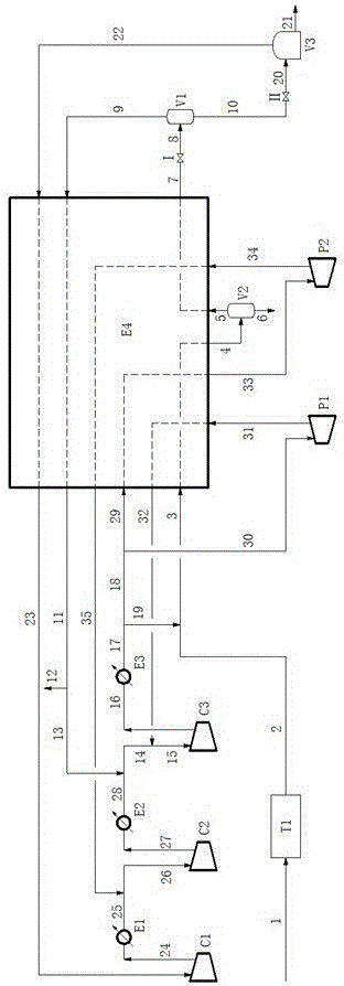
Embodiment 1
[0073] The flow chart of this embodiment is as follows figure 1 As shown, this process includes pretreatment system (T1), expander (P1, P2), cycle gas compressor (C1, C2, C3), cooler (E1, E2, E3), heat exchanger (E4), Heavy hydrocarbon separator (V2), gas-liquid separator (V1), LNG storage tank (V3), throttle valve I, throttle valve II, etc., the methane-rich gas liquefaction system and open cycle are formed through pipelines between each component Cooling System.
[0074] The working steps of this embodiment are as follows:
[0075] (1) Liquefaction of methane-rich gas:
[0076] The untreated methane-enriched raw material gas 1 is processed by the pretreatment system T1 to obtain the methane-enriched raw material gas 2 . The methane-enriched raw material gas 2 is mixed with part of the preheated gas 19 (mentioned below) to obtain the material 3, which is cooled in the heat exchanger E4 to obtain the material 4. Material 4 exits heat exchanger E4 and enters heavy hydrocarb...
Embodiment 2
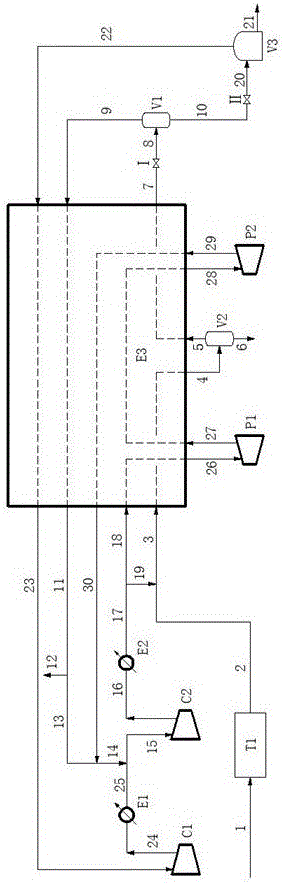
[0082] The flow chart of this embodiment is as follows figure 2 As shown, this process includes pretreatment system (T1), expander (P1, P2), cycle gas compressor (C1, C2), cooler (E1, E2), heat exchanger (E3), heavy hydrocarbon separator (V2), gas-liquid separator (V1), LNG storage tank (V3), throttle valve I, throttle valve II, etc., the methane-enriched gas liquefaction system and open cycle refrigeration system are formed through pipelines between each component.
[0083] The working steps of this embodiment are as follows:
[0084] (1) Liquefaction of methane-rich gas:
[0085]The untreated methane-enriched raw material gas 1 is processed by the pretreatment system T1 to obtain the methane-enriched raw material gas 2 . The methane-enriched raw material gas 2 is mixed with part of the preheated gas 19 (mentioned below) to obtain the material 3, and the material 3 is cooled in the heat exchanger E3 to obtain the material 4. Material 4 exits heat exchanger E3 and enters h...
Embodiment 3
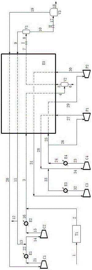
[0091] The flow chart of this embodiment is as follows image 3 As shown, this process includes pretreatment system (T1), expanders (P1, P2), methane flash gas compressors (C1, C2), methane-enriched cycle gas compressors (C3, C4), coolers (E1, E2 , E3, E4), heat exchanger (E5), separator (V1), heavy hydrocarbon separator (V2), LNG storage tank (V3), throttle valve I, throttle valve II, etc. The pipeline constitutes a methane-rich gas liquefaction system and a closed cycle refrigeration system.
[0092] The working steps of this embodiment are as follows:
[0093] (1) Liquefaction of methane-rich gas:
[0094] The untreated methane-enriched raw material gas 1 is processed by the pretreatment system T1 to obtain the methane-enriched raw material gas 2 . The methane-enriched feed gas 2 is mixed with the preheated gas 16 to obtain the material 3, which is cooled in the heat exchanger E5 to obtain the material 4. The material 4 exits the heat exchanger E5 and enters the heavy h...
PUM
 Abstract
Description
Claims
Application Information