Staggered PCD milling cutter used for processing reinforced fiber polymer and method

A composite material and reinforced fiber technology, used in milling cutters, metal processing equipment, manufacturing tools, etc., can solve the problems of fast tool wear, low processing efficiency, delamination of the machined surface, tearing and burr defects, etc. Fewer defects, high cutting efficiency, and improved surface quality

Inactive Publication Date: 2016-08-10
HARBIN UNIV OF SCI & TECH
View PDF9 Cites 20 Cited by
  • Summary
  • Abstract
  • Description
  • Claims
  • Application Information

AI Technical Summary

Problems solved by technology

[0003] The purpose of the present invention is to provide a kind of staggered PCD milling cutter and method for processing reinforced fiber composite materials, to solve the problem of usin

Method used


Image

  • Staggered PCD milling cutter used for processing reinforced fiber polymer and method
  • Staggered PCD milling cutter used for processing reinforced fiber polymer and method
  • Staggered PCD milling cutter used for processing reinforced fiber polymer and method

Examples


specific Embodiment approach 1

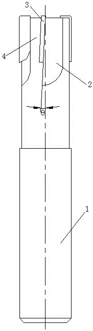
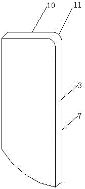
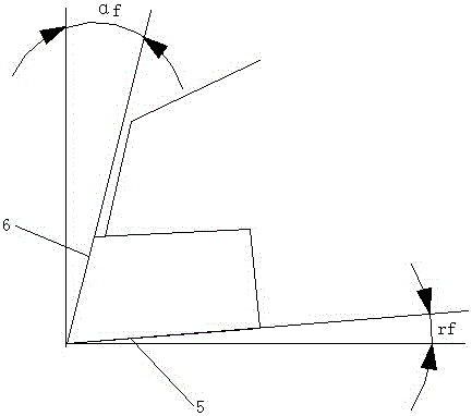
[0023] Specific implementation mode one: as Figure 1~Figure 5 As shown, this embodiment discloses a staggered PCD milling cutter for processing reinforced fiber composite materials, including a cemented carbide cutter body 1, and the front end of the outer peripheral surface of the cemented carbide cutter body 1 is provided with four milling cutters. Insert groove 2 and four chip removal grooves 4, described a kind of staggered PCD milling cutter for processing reinforced fiber composite material also includes four PCD milling blades 3, described four milling blade grooves 2 all It is arranged obliquely, and a PCD milling insert 3 is welded in each of the milling insert slots 2, and the same clips are arranged between the four PCD milling inserts 3 and the central axis of the cemented carbide cutter body 1. Angle θ, and every two adjacent PCD milling inserts 3 have opposite inclination directions (forming a scissors-like cutting during milling), and the eccentric edges of eve...

specific Embodiment approach 2

[0026] Specific implementation mode two: as figure 1 As shown in the first embodiment, a staggered PCD milling cutter for processing reinforced fiber composite materials, each of the PCD milling blades 3 axially extends beyond the front end of the cemented carbide cutter body 1 is an end tooth, and the radially outermost surface of each PCD milling insert 3 is a peripheral tooth. Peripheral teeth are used for side milling, while end teeth are used for face milling.

specific Embodiment approach 3

[0027] Specific implementation mode three: as figure 1 As shown in the first embodiment, a staggered PCD milling cutter for processing reinforced fiber composite materials, the included angle θ between each of the PCD milling blades 3 and the central axis of the cemented carbide cutter body 1 Both are 3°~5°. Angling reduces axial force and reduces delamination when milling workpieces.


PUM

PropertyMeasurementUnit
Widthaaaaaaaaaa
Lengthaaaaaaaaaa

Abstract

The invention discloses a staggered PCD milling cutter used for processing reinforced fiber polymer and a method, relates to the technical field of milling cutters and solves the problems that when a traditional milling cutter is adopted for processing CFRP, the cutter is rapid to wear, the processing surface is layered and torn, burrs are caused, and the processing efficiency is low. Four milling cutter blade grooves and four chipping grooves are arranged in the front end of the outer circumference of a hard alloy cutter body, wherein the four milling cutter blade grooves are obliquely arranged; a PCD milling cutter blade is welded in each milling cutter blade groove; the oblique directions of every two adjacent PCD milling cutter blades are opposite; the oblique cutting edges of every two PCD milling cutter blades with the same oblique directions are distributed in a staggered way; and the chipping grooves are arranged on one side of front cutter faces of the PCD milling cutter blades and closely adjoin the PCD milling cutter blades. The method comprises the steps of grinding the four chipping grooves and the four milling cutter grooves; welding the four milling cutter blades in the four milling cutter grooves; and grinding the end tooth cutting edges and the peripheral tooth cutting edges of the four PCD milling cutter blades. The staggered PCD milling cutter is used for milling the reinforced fiber polymer.

Description

technical field [0001] The invention relates to the technical field of milling cutters, in particular to an interlaced PCD milling cutter and method for processing reinforced fiber composite materials. Background technique [0002] Carbon fiber composites (CFRP) are widely used in aerospace, energy and chemical industries due to their excellent physical and mechanical properties. CFRP is composed of matrix material and fiber-reinforced material. The strength and hardness of fiber-reinforced material is much higher than that of matrix material. It is a difficult-to-machine material with high cutting force and severe tool wear, which is difficult for traditional tool materials. CFRP is made of carbon fiber layers. During the milling process, once the tool is worn, it is easy to produce defects such as delamination, tearing and burrs, resulting in a high rate of product failure. These problems have become potential safety hazards for parts. Serious The application of CFRP is r...

Claims


Application Information

Patent Timeline
IPC IPC(8): B23C5/10B23P15/34
CPCB23C5/10B23P15/34
Inventor 陈涛杨辰刘献礼王艳艳
Owner HARBIN UNIV OF SCI & TECH
Why Eureka
Try Eureka