Cage pocket structure with stress buffer grooves and pocket machining technology of structure

A stress buffering and processing technology, applied to rotating parts, bearings, shafts and other directions that are resistant to centrifugal force, can solve the problems of complex processing process and large wear of processing tools, shorten the quality gap, improve performance, and ensure stability. Effect

Active Publication Date: 2016-08-10
AVIC HARBIN BEARING
View PDF3 Cites 7 Cited by
  • Summary
  • Abstract
  • Description
  • Claims
  • Application Information

AI Technical Summary

Problems solved by technology

[0004] The present invention aims to solve the problems that the existing cylindrical roller bearing cage pocket structure has a large wear on the machining tool and the processing process is complicated, and further provides a cage pocket structure with stress buffer grooves and its pocket structure. Hole processing

Method used


Image

  • Cage pocket structure with stress buffer grooves and pocket machining technology of structure
  • Cage pocket structure with stress buffer grooves and pocket machining technology of structure
  • Cage pocket structure with stress buffer grooves and pocket machining technology of structure

Examples


specific Embodiment approach 1

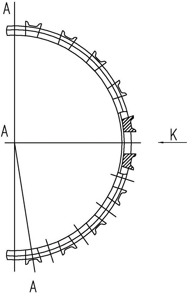
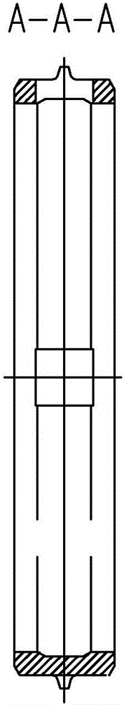
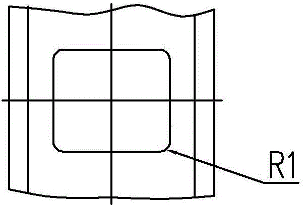
[0025] Specific implementation mode one: combine Figure 1 to Figure 10 Describe this embodiment, a cage pocket structure with stress buffering grooves, the pockets are straight pockets, and stress buffering grooves with a radius of R2 are processed at the four corners of the pockets.

[0026] At present, cages with stress buffer grooves in the pockets have been applied on Type 3 bearings, and all of them have been developed and processed. After testing, the surface finish of the pockets is Ra0.16~0.19μ, and the position accuracy of the pockets and the stress buffer grooves are protruding. The quantity meets the product requirements, and the consistency of precision and dimensional values ​​is good. Type 3 bearings have passed the verification of the tester after assembly and meet the bearing performance requirements. The application of this process technology has raised the short cylindrical roller bearing pocket process technology to a new level, and the processing quality ...

specific Embodiment approach 2

[0028] Specific implementation mode two: combination Figure 8 ~ Figure 10 To describe this embodiment, the value of the radius R2 of the stress buffer groove is between 0.75 mm and 1 mm. With this design, on the one hand, the chamfering of the four walls of the pocket is easy to control and ensure that the chamfering of the four walls is smooth after machining of the pocket, avoiding stress concentration; on the other hand, the machining method of the pocket can be changed from broaching to milling, improving the pocket Processing quality. Other compositions and connections are the same as those in the first embodiment.

specific Embodiment approach 3

[0029] Specific implementation mode three: combination Figure 1 to Figure 10 Describe this embodiment, a pocket hole processing process for the cage pocket structure with stress buffer grooves described in the first or second specific embodiment, the steps are as follows:

[0030] 1. Select the drill bit with the same radius value as the stress buffer groove required by the drawing, and use this drill bit to perform stress buffer grooves on the pocket of the cylindrical roller bearing cage on the CNC machining center according to the position of the stress buffer groove required by the drawing. processing;

[0031] 2. Drill the cage on the CNC machining center according to the center position of the pocket hole required by the drawing, and the drilling size should ensure that the unilateral milling allowance is 0.1mm to 0.25mm;

[0032] 3. On the CNC machining center, use the milling cutter to move the tool from the center of the pocket hole, and complete the pocket hole pro...


PUM

PropertyMeasurementUnit
radiusaaaaaaaaaa
radiusaaaaaaaaaa
diameteraaaaaaaaaa

Abstract

The invention discloses a cage pocket structure with stress buffer grooves and a pocket machining technology of the structure. The problems that an existing cylindrical roller bearing cage pocket structure is large in abrasion to a machining tool and complex in machining technology process are solved. The cage pocket structure with the stress buffer grooves is characterized in that the pocket is a straight pocket, and the stress buffer grooves with the radius of R2 are machined on the four corners of the pocket; according to the pocket machining technology of the cage pocket structure with the stress buffer grooves, a drill bit is selected, and according to the stress buffer groove positions required by the drawing, on a numerical control machining center, the drill bit is used for carrying out stress buffer groove machining on the pocket of a cylindrical roller bearing cage; the cage is drilled on the numerical control machining center, and the drilling size should ensure that the single-side milling allowance ranges from 0.1 mm to 0.25 mm; a milling cutter is used for feeding from the center of the pocket, and pocket machining is completed through milling; and the machined pocket is detected. The cage pocket structure is used for machining of the cage pocket.

Description

technical field [0001] The invention relates to a retainer pocket, in particular to a retainer pocket structure with a stress buffer groove and a pocket processing technology thereof. Background technique [0002] Short cylindrical roller bearings are widely used in aeroengine main shaft bearings. The cages are mostly 40CrNiMoA, and the quenched and tempered hardness is HRC33-37. The process flow framework of this type of cage is: rough turning plane, outer diameter, inner diameter → quenching and tempering → final turning plane, outer diameter, inner diameter → drilling and milling holes → drawing square holes → deburring → finishing → cleaning, processing process cumbersome. [0003] Usually short cylindrical roller bearing cage pockets are straight pockets (such as figure 1 ) and milling and drawing pockets (such as figure 2 ) Two structures, using horizontal or vertical broaching to complete the final processing. There are many factors that affect the manufacturing ...

Claims


Application Information

Patent Timeline
Patent Type & Authority Applications(China)
IPC IPC(8): F16C33/46B23P15/14
CPCB23P15/14F16C33/46F16C2220/62F16C2220/66F16C33/4629F16C2360/23
Inventor 李迎丽孙慧广王涛寇思源石东丹毕立行李宝玉
Owner AVIC HARBIN BEARING
Why Eureka
Try Eureka