Pocket Hole Processing Technology of Cage Pocket Structure with Stress Buffering Groove
A stress buffering and processing technology, applied to rotating parts, bearings, shafts and other directions that are resistant to centrifugal force, can solve the problems of poor surface quality and large wear of processing tools, shorten the quality gap, improve performance, and ensure stability. Effect
- Summary
- Abstract
- Description
- Claims
- Application Information
AI Technical Summary
Problems solved by technology
Method used
Image
Examples
specific Embodiment approach 1
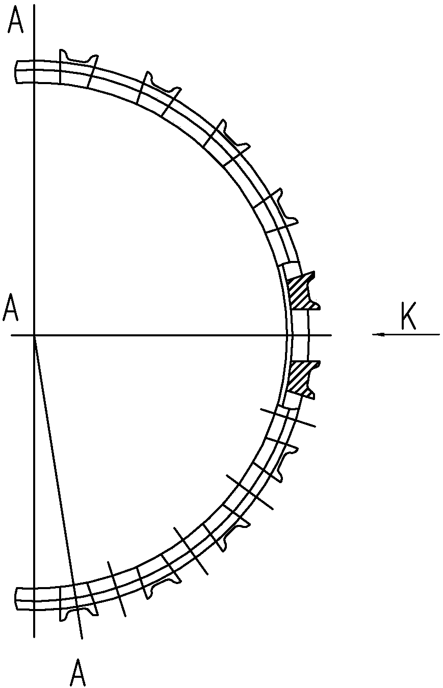
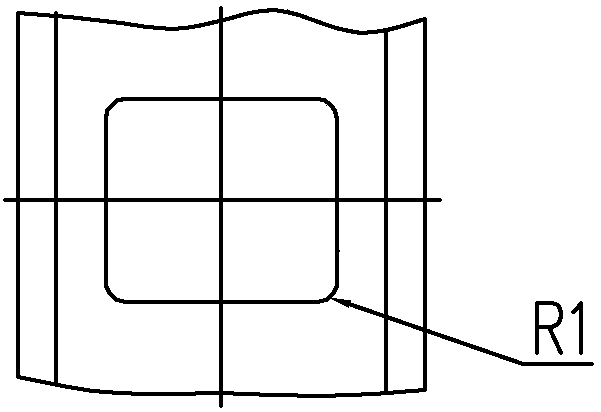
[0025] Specific implementation mode one: combine Figure 1 to Figure 10 Describe this embodiment, a cage pocket structure with stress buffering grooves, the pockets are straight pockets, and stress buffering grooves with a radius of R2 are processed at the four corners of the pockets.
[0026] At present, cages with stress buffer grooves in the pockets have been applied on Type 3 bearings, and all of them have been developed and processed. After testing, the surface finish of the pockets is Ra0.16~0.19μ, and the position accuracy of the pockets and the stress buffer grooves are protruding. The quantity meets the product requirements, and the consistency of precision and dimensional values is good. Type 3 bearings have passed the verification of the tester after assembly and meet the bearing performance requirements. The application of this process technology has raised the short cylindrical roller bearing pocket process technology to a new level, and the processing quality ...
specific Embodiment approach 2
[0028] Specific implementation mode two: combination Figure 8 ~ Figure 10 To describe this embodiment, the value of the radius R2 of the stress buffer groove is between 0.75 mm and 1 mm. With this design, on the one hand, the chamfering of the four walls of the pocket is easy to control and ensure that the chamfering of the four walls is smooth after machining of the pocket, avoiding stress concentration; on the other hand, the machining method of the pocket can be changed from broaching to milling, improving the pocket Processing quality. Other compositions and connections are the same as those in the first embodiment.
specific Embodiment approach 3
[0029] Specific implementation mode three: combination Figure 1 to Figure 10 Describe this embodiment, a pocket hole processing process for the cage pocket structure with stress buffer grooves described in the first or second specific embodiment, the steps are as follows:
[0030] 1. Select the drill bit with the same radius value as the stress buffer groove required by the drawing, and use this drill bit to perform stress buffer grooves on the pocket of the cylindrical roller bearing cage on the CNC machining center according to the position of the stress buffer groove required by the drawing. processing;
[0031] 2. Drill the cage on the CNC machining center according to the center position of the pocket hole required by the drawing, and the drilling size should ensure that the unilateral milling allowance is 0.1mm to 0.25mm;
[0032] 3. On the CNC machining center, use the milling cutter to move the tool from the center of the pocket hole, and complete the pocket hole pro...
PUM
| Property | Measurement | Unit |
|---|---|---|
| radius | aaaaa | aaaaa |
| diameter | aaaaa | aaaaa |
| diameter | aaaaa | aaaaa |
Abstract
Description
Claims
Application Information
 - R&D
- Intellectual Property
- Life Sciences
- Materials
- Tech Scout
- Unparalleled Data Quality
- Higher Quality Content
- 60% Fewer Hallucinations
Browse by: Latest US Patents, China's latest patents, Technical Efficacy Thesaurus, Application Domain, Technology Topic, Popular Technical Reports.
© 2025 PatSnap. All rights reserved.Legal|Privacy policy|Modern Slavery Act Transparency Statement|Sitemap|About US| Contact US: help@patsnap.com


