Heat pump air-conditioning system of fuel cell vehicle and heating and refrigeration method

A fuel cell, heat pump air conditioning technology, applied in heating/cooling equipment, vehicle components, air handling equipment, etc., can solve the problems of energy loss, small heat supply, increased maintenance cost, etc., to improve utilization efficiency, wide range of sources, low noise effect

Active Publication Date: 2016-08-17
GUANGDONG HYDROGEN ENERGY SCI & TECH
View PDF12 Cites 9 Cited by
  • Summary
  • Abstract
  • Description
  • Claims
  • Application Information

AI Technical Summary

Problems solved by technology

[0005] However, the disadvantage of the heat pump air conditioning system for vehicles is that the lower the outside air temperature is, the smaller the heat supply is, especially when the outside air temperature is lower than -5°C, the heat pump cannot work normally, and electricity or other auxiliary equipment is required. The heat source heats the air, and the efficiency of the heat pump is greatly reduced
In the heating condition of the vehicle heat pump air conditioning system, frost will form on the evaporator, and regular defrosting is required. The defrosting module technology can refer to Chinese patent application 201210152219.4 for defrosting method for air source heat pump system, 201410108455.5 for a heat pump Air-conditioning defrosting control method and heat pump air-conditioning system, after the air source heat pump adds a defrosting module, not only the stability is reduced, the maintenance cost is increased, but also a considerable part of energy is lost

Method used


Image

  • Heat pump air-conditioning system of fuel cell vehicle and heating and refrigeration method
  • Heat pump air-conditioning system of fuel cell vehicle and heating and refrigeration method

Examples


Embodiment Construction

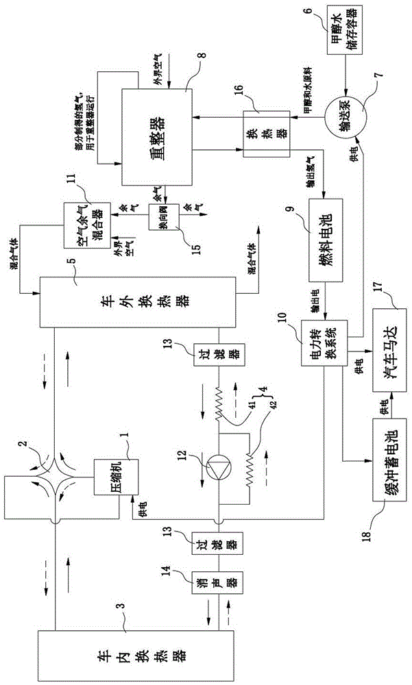
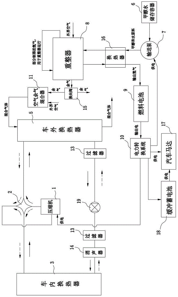
[0023] The structural principle and working principle of the present invention will be further described in detail below in conjunction with the accompanying drawings.

[0024] Such as figure 1 and figure 2 As shown, a heat pump air-conditioning system for a fuel cell vehicle includes a compressor 1, a four-way reversing valve 2, an interior heat exchanger 3, a throttle valve 4, an exterior heat exchanger 5, a methanol water storage container 6, Delivery pump 7, reformer 8, fuel cell 9, power conversion system 10, automobile motor 17 and residual air mixer 11; the compressor 1, four-way reversing valve 2, in-vehicle heat exchanger 3, section The working fluid delivery circuit of the heat pump air conditioner is formed between the flow valve 4 and the external heat exchanger 5. figure 1In the working fluid delivery circuit, the dotted arrow indicates the heating condition, and the solid arrow indicates the cooling condition; the methanol-water storage container 6 stores liqu...


PUM


Abstract

The invention discloses a heat pump air-conditioning system of a fuel cell vehicle. The heat pump air-conditioning system comprises a compressor, a four-way reversing valve, a vehicle interior heat exchanger, a throttling valve, a vehicle exterior heat exchanger, a methanol water storage container, a conveying pump, a reformer, a fuel cell, a power conversion system, a vehicle motor and a residual air mixer, wherein the reformer generates high-temperature residual air and discharges the residual air to the residual air mixer or the outside; the residual air mixer is used for mixing external air with the high-temperature residual air to produce intermediate-temperature mixed air and outputting the intermediate-temperature mixed air to the outside; the fuel cell is used for generating electric energy through an electrochemical reaction between hydrogen and oxygen and outputting the electric energy; the power conversion system is used for converting the electric energy output by the fuel cell into electricity required by a load to supply power to the compressor, the conveying pump and the vehicle motor. The heat pump air-conditioning system can still efficiently and normally work under a heating working condition, when the outdoor air is lower than 5 DEG C, an evaporator cannot frost, power demands of the vehicle motor can be met, the noise and the energy consumption are low, and air and environment cannot be polluted.

Description

technical field [0001] The invention relates to the technical field of automobile air-conditioning, in particular to a heat pump air-conditioning system and a heating and cooling method for a fuel cell automobile. Background technique [0002] At present, the vast majority of automobiles use gasoline and diesel as fuel, which not only consumes a large amount of oil resources, but also causes serious air pollution due to automobile exhaust. In response to this resource problem and environmental problem, the development of electric vehicles has become very important. An electric vehicle refers to a vehicle powered by an on-board power supply and driven by a motor to drive the wheels. Electric vehicles include pure electric vehicles, hybrid vehicles and fuel cell vehicles. In the prior art, a fuel cell vehicle refers to an electric vehicle equipped with a fuel cell as a power source for driving power. For the technology of a fuel cell vehicle, please refer to the patent 20141...

Claims


Application Information

Patent Timeline
Patent Type & Authority Applications(China)
IPC IPC(8): B60H1/00
CPCB60H1/00321B60H1/00392B60H1/00428Y02T10/88
Inventor 向华
Owner GUANGDONG HYDROGEN ENERGY SCI & TECH
Why Eureka
Try Eureka