Dynamic membrane anaerobic-aerobiotic wastewater treatment method based on microbiological fuel cell

A sewage treatment method and fuel cell technology, applied in the field of sewage treatment, can solve the problems of high investment cost, low efficiency, and large equipment footprint, and achieve the effects of high operating costs, increased concentration, and large power consumption

Inactive Publication Date: 2016-08-17
XIAMEN UNIV
View PDF6 Cites 9 Cited by
  • Summary
  • Abstract
  • Description
  • Claims
  • Application Information

AI Technical Summary

Problems solved by technology

[0004] The purpose of the present invention is to provide a dynamic membrane anaerobic-aerobic sewage treatment device based on microbial fuel cells to solve the existing problems of low efficiency, large equipment footprint, and high investment costs in the existing sewage treatment

Method used


Image

  • Dynamic membrane anaerobic-aerobiotic wastewater treatment method based on microbiological fuel cell
  • Dynamic membrane anaerobic-aerobiotic wastewater treatment method based on microbiological fuel cell

Examples


Embodiment I

[0043] Embodiment I (1~3)

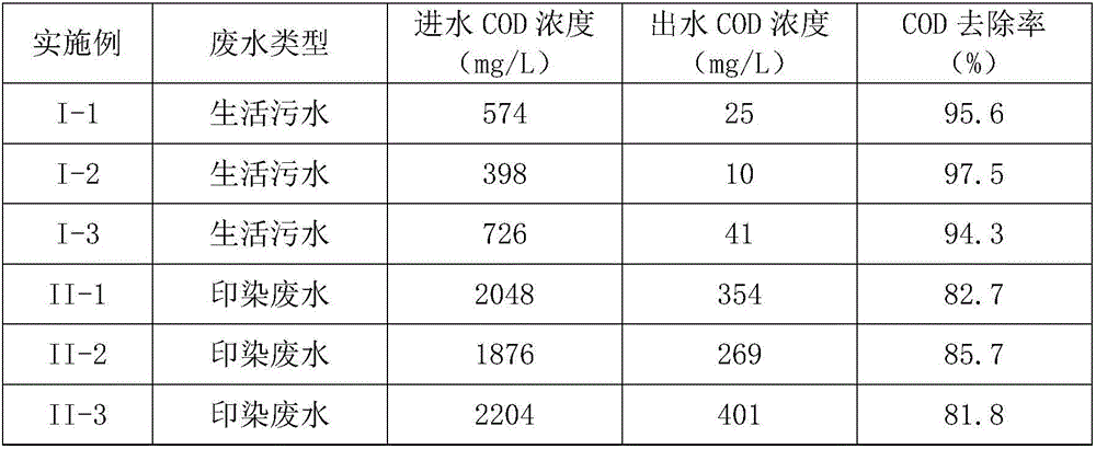
[0044] Type of waste water: Domestic sewage. According to the influent organic load, the hydraulic retention time and circulation flow rate are determined, so that the domestic sewage is circulated through the dynamic membrane in the anaerobic tank and the aerobic tank respectively to complete the degradation of anaerobic and aerobic microorganisms, and the different degradation times are measured. COD, SS, DO, pH value, temperature and other indicators of the water body in the pool.

Embodiment II

[0045] Embodiment II (1~3)

[0046] Wastewater type: printing and dyeing wastewater. According to the influent organic load, the hydraulic retention time and circulation flow rate are determined, so that the domestic sewage is circulated through the dynamic membrane in the anaerobic tank and the aerobic tank respectively to complete the degradation of anaerobic and aerobic microorganisms, and the different degradation times are measured. COD, SS, DO, pH value, temperature and other indicators of the water body in the pool.

[0047] The domestic sewage and printing and dyeing wastewater treatment effects of Embodiment I and Embodiment II are shown in Table 1.

[0048] Table 1

[0049]

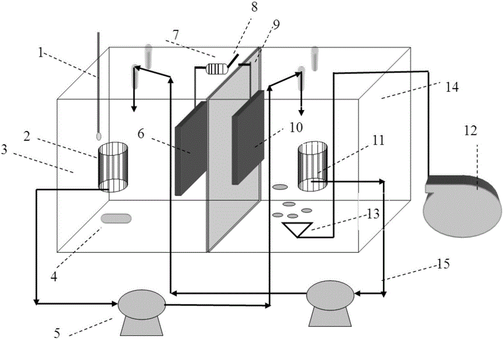
[0050] In order to realize the standard discharge of waste water, recycle electric energy and realize the effective utilization of resources, the present invention combines microbial fuel cell technology and dynamic membrane technology to realize the simultaneous degradation of pollutants i...


PUM

PropertyMeasurementUnit
electrical resistanceaaaaaaaaaa
quality scoreaaaaaaaaaa

Abstract

The invention relates to wastewater treatment, in particular to a dynamic membrane anaerobic-aerobiotic wastewater treatment method based on a microbiological fuel cell. A treatment device is provided with an anode chamber, a cathode chamber and an aeration device, the anode chamber is provided with a temperature gauge, a stirring device and an anode, and the cathode chamber is provided with an aerator and a cathode. Raw water enters an anaerobic-anode tank and an aerobiotic-cathode tank, and sludge is discharged from the bottom of the anaerobic-anode tank; a perforated aeration pipe is arranged in the aerobiotic-cathode tank in a penetrating mode, and sludge is discharged from the bottom; dynamic membrane assemblies are placed in the anaerobic-anode tank and the aerobiotic-cathode tank, and wastewater in the anaerobic-anode tank is pumped into the aerobiotic-cathode tank through a constant-flow pump via a water outlet of the corresponding dynamic membrane assembly; wastewater in the aerobiotic-cathode tank is pumped back into the anaerobic-anode tank through a constant-flow pump via a water outlet of the corresponding dynamic membrane assembly, so that wastewater in the anaerobic-anode tank and wastewater in the aerobiotic-cathode tank are simultaneously, continuously and circularly treated in time and space, and the wastewater treatment process is completed; the water inlet flow velocity and the circulation flow velocity are controlled through the constant-flow pumps, and outlet water is discharged after reaching the standard.

Description

technical field [0001] The invention relates to sewage treatment, in particular to a dynamic membrane anaerobic-aerobic sewage treatment method based on microbial fuel cells. Background technique [0002] With the rapid development of industrial technology, industrial wastewater discharged from printing and dyeing, chemical, food, paper and other industries has become one of the problems that need to be solved urgently in the field of sewage treatment. In recent years, the wastewater biological treatment technology has changed from the traditional single anaerobic method and aerobic method to the anaerobic-aerobic combined treatment method, but there are problems such as large amount of residual sludge, high energy consumption, and large occupied area. Membrane-bioreactor technology (MBR) is a new system that combines membrane separation technology and wastewater biological treatment technology. This system uses membrane separation technology to replace the secondary sedimen...

Claims


Application Information

Patent Timeline
Patent Type & Authority Applications(China)
IPC IPC(8): C02F3/30
CPCC02F3/30C02F3/005
Inventor 王海涛李薇
Owner XIAMEN UNIV
Why Eureka
Try Eureka