Disposable carbon dioxide cracking device and manufacturing method thereof
A carbon dioxide, one-time technology, applied in the direction of earthwork drilling, lifting valve, sliding valve, etc., can solve the problems of heavy weight, difficult recycling, laborious transportation, etc., to achieve easy portability and transportation, simple and easy operation, and reduce recycling The effect of work
- Summary
- Abstract
- Description
- Claims
- Application Information
AI Technical Summary
Problems solved by technology
Method used
Image
Examples
Embodiment 1
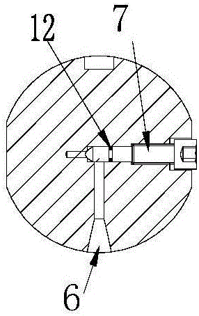
[0030] refer to figure 1 , 2 , 3, refer to figure 1 , 2 , 3. The present embodiment includes an expansion tube 2, an activator 3, an upper plug 4, and a locking device 5. The expansion tube 2 and the upper plug 4 form an airtight container, and the activator 3 is located in the airtight container; the upper plug There is an installation opening for installing the activator 3 on the head 4, and the locking device 5 seals the installation opening; the liquid filling hole 6 is provided with a lock valve to control the liquid filling on and off; the expansion pipe is mainly composed of a pipe body and a lower end cover 1 , The filling hole is located on the lower end cap 1 of the expansion tube. There is a liquid filling hole 6 on the cylindrical surface of the lower end cover 1. The liquid filling hole is composed of a radial hole 10 and an axial hole 11. The locking valve is a stepped locking spool 7, which is set at In the stepped valve cavity hole, the valve cavity hole is...
Embodiment 2
[0037] refer to Figure 4 , 5 , 6. This embodiment is basically the same as Embodiment 1, the difference is that the positions and structures of the filling hole and the lock valve are different, the filling hole is on the upper plug 4a, and the filling hole is an axial step Circular hole 18, the lock valve is a stepped lock spool. The stepped circular hole 18 is made up of large hole sections and small hole sections with different inner diameters. Hole 20; the locking spool is made up of a valve seat 19 with a large diameter and a valve head 13 with a small diameter. The valve seat 19 is a hollow valve seat with an open bottom, on which an O-ring 12a is arranged.
Embodiment 3
[0039] refer to Figure 7 , 8, this embodiment is basically the same as Embodiment 2, the difference is that the structure of the liquid filling hole and the blocking valve is different, the liquid filling hole is opened on the upper plug 4c, the liquid filling hole is an axial stepped circular hole, and the blocking valve The valve is a spring ball valve, the large hole section of the stepped circular hole is a cylindrical hole facing the inner cavity of the expansion tube, and a spring 21 and a ball valve core 22 are housed in it, and the small hole section of the stepped circular hole is a threaded hole 23 facing the outside.
PUM
 Abstract
Description
Claims
Application Information
 - R&D
- Intellectual Property
- Life Sciences
- Materials
- Tech Scout
- Unparalleled Data Quality
- Higher Quality Content
- 60% Fewer Hallucinations
Browse by: Latest US Patents, China's latest patents, Technical Efficacy Thesaurus, Application Domain, Technology Topic, Popular Technical Reports.
© 2025 PatSnap. All rights reserved.Legal|Privacy policy|Modern Slavery Act Transparency Statement|Sitemap|About US| Contact US: help@patsnap.com


