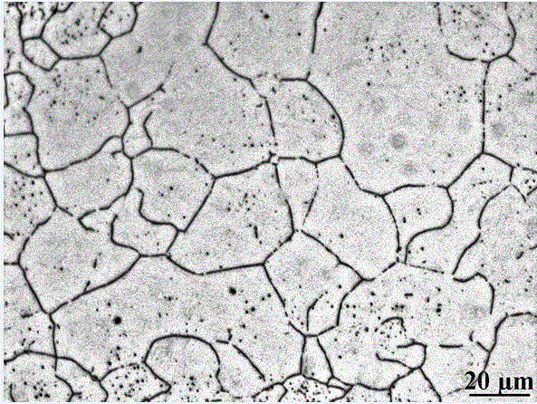
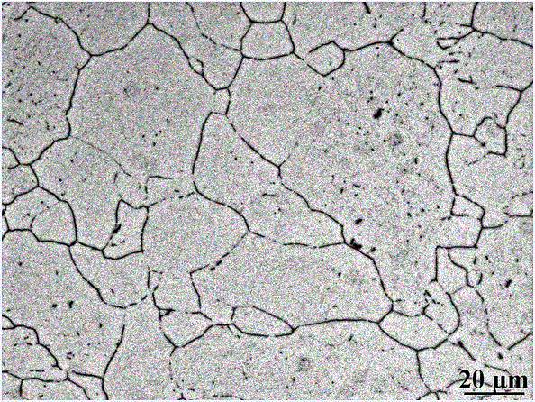
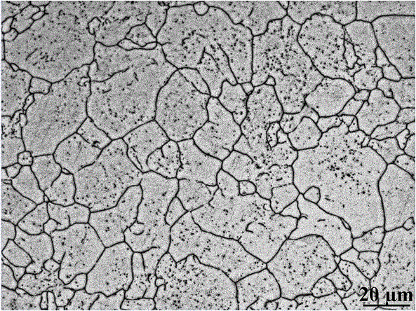
Method for displaying original austenite grain boundary of 85Cr2MnMo liner steel

A technology of austenite grain boundary and lining plate, which is applied in the field of heat treatment quality inspection, can solve problems such as unsatisfactory display effect, and achieve the effect of clear display effect and high efficiency

Active Publication Date: 2016-08-17
SHANGHAI UNIV
View PDF2 Cites 11 Cited by
  • Summary
  • Abstract
  • Description
  • Claims
  • Application Information

AI Technical Summary

Problems solved by technology

However, for 85Cr2MnMo liner steel, the display effect of the above-mentioned corrosive agents is not ideal

Method used


Image

  • Method for displaying original austenite grain boundary of 85Cr2MnMo liner steel
  • Method for displaying original austenite grain boundary of 85Cr2MnMo liner steel
  • Method for displaying original austenite grain boundary of 85Cr2MnMo liner steel

Examples


Embodiment 1

[0021] The chemical composition of the sample in this example is C: 0.83%, Si: 0.43%, Mn: 0.77%, Cr: 1.91%, Mo: 0.34%, Ni: 0.12%, P: 0.035%, S: 0.028%, The rest is Fe and unavoidable impurities. Specific steps are as follows:

[0022] A. sample. Cut two heat treatment test blocks with a size of 10×10×15mm and three thermal expansion samples with a size of ϕ4×10mm from an industrially produced liner. The roughness of the two ends of the thermal expansion sample is Ra0.8, and the two ends must be parallel to each other and perpendicular to the axis of the round rod.

[0023] B. Measure the critical point. According to the parameters stipulated in the standard "YB / T 5127-93" for determining the critical point of steel by dilation method, its Accm (cementite and carbide are completely dissolved into austenite) temperature is measured to be about 835 °C.

[0024] C. Quenching treatment. Put the samples into the heating furnace in batches and place them as close as possible ...

Embodiment 2

[0027] The chemical composition of the sample in this example is C: 0.79%, Si: 0.39%, Mn: 0.85%, Cr: 1.90%, Mo: 0.36%, Ni: 0.10%, P: 0.029%, S: 0.014%, Nb: 0.1%, the rest is Fe and unavoidable impurities. Specific steps are as follows:

[0028] A. Sample preparation. Cut two heat treatment test blocks with a size of 10×10×15mm and three thermal expansion samples with a size of ϕ4×10mm from an industrially produced liner. The roughness of the two ends of the thermal expansion sample is Ra0.8, and the two ends must be parallel to each other and perpendicular to the axis of the round rod.

[0029] B. Measure the critical point. According to the parameters stipulated in the standard "YB / T5127-93" for determining the critical point of steel by dilation method, its Accm (cementite and carbide are completely dissolved into austenite) temperature is measured to be about 835 °C.

[0030] C. Quenching treatment. Put the samples into the heating furnace in batches, and place them as...


PUM


Abstract

The invention discloses a method for displaying the original austenite grain boundary of 85Cr2MnMo liner steel. The method comprises the following steps: (1) sample preparation; (2) determination of phase transition temperature, wherein Accm (complete dissolution of cementite and carbide into austenite) temperature of the 85Cr2MnMo liner steel is 835 DEG C according to results of thermal expansion measurement; (3) quenching: heating a sample to 860 to 920 DEG C, maintaining the temperature for 60 min and then rapidly quenching the sample in machine oil No. 10; and (4) corrosion: mixing 100 ml of deionized water, 4 g of picric acid, 2 g of Aiou shampoo paste and 0.1 g of CuCl2.2H2O to prepare a corrosive agent, putting the corrosive agent in a water-bath pot with a temperature of 55 to 60 DEG C for heat preservation, putting the quenched, ground and polished sample in the corrosive agent for corrosion for 50 to 60 s, taking the sample out, wiping the sample with absorbent cotton dipped with alcohol so as to remove reaction products on the surface of the sample, cleaning the sample through flushing and then subjecting the sample to blow-drying. As the sample is observed with an optical microscope, the original austenite grain boundary of 85Cr2MnMo liner steel can be clearly displayed and matrix structure is not displayed, so bases are provided for accurate rating of the grain size of austenite.

Description

technical field [0001] The invention belongs to the technical field of heat treatment quality detection, and in particular relates to a method for clearly displaying 85Cr2MnMo original austenite grain boundaries. Background technique [0002] During the heat treatment process, the original austenite grain size of the steel directly affects the mechanical properties of the steel. Steel with fine austenite grains has high strength and toughness; steel with coarse austenite grains has low strength, poor plasticity, and increased brittleness, and the manufactured parts are prone to accidents such as fracture and early failure during use; Coarse-grained steel is easy to deform and crack during quenching, so it is of great significance to accurately display the austenite grains of steel. [0003] There are many methods for characterizing the prior-austenite grain boundaries of steel. Lan Yingbin et al. clearly displayed the austenite grain boundaries of 20CrMnTi, 35CrMo and 40Cr...

Claims


Application Information

Patent Timeline
Patent Type & Authority Applications(China)
IPC IPC(8): G01N1/32G01N21/84
CPCG01N1/32G01N21/84G01N2021/8477
Inventor 徐扬陈湘茹徐阳危志强许婕徐智帅翟启杰
Owner SHANGHAI UNIV
Why Eureka
Try Eureka