Protection circuit for lightning surge

A protection circuit and surge technology, applied in emergency protection circuit devices, circuit devices, emergency protection circuit devices for limiting overcurrent/overvoltage, etc., can solve the problem that the protection circuit effect is not particularly ideal, AC-DC switching power supply Harm, cost and volume increase, etc., to achieve the effect of improving EMI) performance, saving space, and improving effect

Inactive Publication Date: 2016-08-17
MORNSUN GUANGZHOU SCI & TECH
View PDF9 Cites 8 Cited by
  • Summary
  • Abstract
  • Description
  • Claims
  • Application Information

AI Technical Summary

Problems solved by technology

Since the AC-DC switching power supply is connected to the mains, the mains is often affected by some natural factors (such as lightning strikes) and application environments (such as the opening or closing of large inductive or capacitive loads on the mains). break), resulting in an instantaneous voltage or current peak, superimposed on the mains, causing great harm to the AC-DC switching power supply
The existing AC-DC switching power supply will add a lightning surge protection circuit at the input end to suppress this part of the hazard and ensure the safe and reliable use of the product. However, adding this part of the circuit will inevitably increase the number of components, resulting in an increase in cost. The higher the surge protection requirements, the more devices are added, and the higher the cost
[0003] The lightning surge protection circuit of the prior art is as figure 1 As sh

Method used


Image

  • Protection circuit for lightning surge
  • Protection circuit for lightning surge
  • Protection circuit for lightning surge

Examples


specific Embodiment approach 1

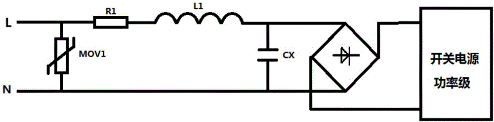
[0027] Such as figure 2 As shown, the lightning surge protection circuit of this embodiment includes a first discharge circuit composed of a piezoresistor MOV1 and a resistor R1, a noise filter circuit composed of a differential mode inductor L1 and a safety X capacitor CX.

[0028] One end of the varistor MOV1 is connected to the input end L of the AC power line and at the same time connected to one end of the resistor R1, the other end of the varistor MOV1 is connected to the input end N of the AC power line; the other end of the resistor R1 is connected to the One end of the differential mode inductor L1 is connected; the other end of the differential mode inductor L1 is connected to one end of the safety X capacitor CX; the other end of the safety X capacitor CX is connected to the other end of the varistor MOV1 The safety X capacitor CX is also connected in parallel to the AC input terminal of the rectifier bridge; the positive and negative output lines of the rectifier ...

specific Embodiment approach 2

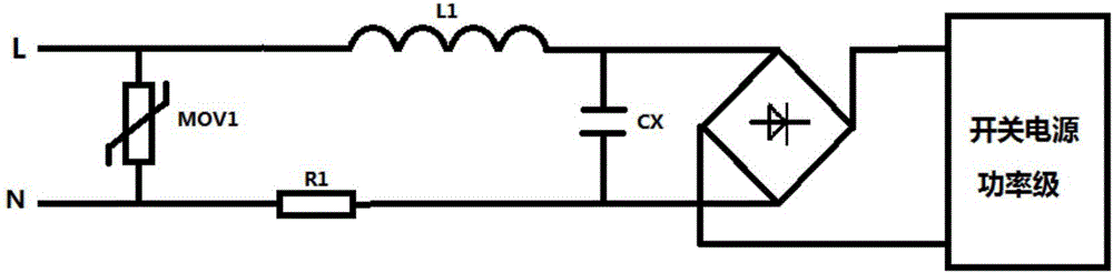
[0036] The difference between this specific embodiment and the first specific embodiment is that the position of the first discharge circuit is changed after the rectifier bridge.

[0037] Such as Figure 4 The lightning surge protection circuit shown includes a noise filter circuit composed of a differential mode inductor L1 and a safety X capacitor CX, and a first discharge circuit composed of a piezoresistor MOV1 and a resistor R1.

[0038] One end of the differential mode inductor L1 is connected to the input end L of the power line, and the other end of the differential mode inductor L1 is connected to one end of the safety X capacitor CX; the other end of the safety X capacitor CX is connected to the power line input N , the safety X capacitor CX is also connected in parallel to the AC input terminal of the rectifier bridge; the varistor MOV1 is connected in parallel to the positive and negative output lines of the rectifier bridge; one end of the resistor R1 is connecte...

specific Embodiment approach 3

[0041] The difference between this specific embodiment and specific embodiment 1 is that this specific embodiment adopts a two-stage bleeder, that is, a first-stage bleeder circuit is added after the noise filter circuit.

[0042] Such as Figure 5 Shown is the lightning surge protection circuit of this embodiment, which includes a first discharge circuit composed of a piezoresistor MOV1 and a resistor R1, a second discharge circuit composed of a piezoresistor MOV2 and a resistor R2, and a differential mode inductance L1 and an amplifier. A noise filter circuit composed of a gauge X capacitor CX.

[0043] One end of the varistor MOV1 is connected to the input end L of the AC power line and at the same time connected to one end of the resistor R1, the other end of the varistor MOV1 is connected to the input end N of the AC power line; the other end of the resistor R1 is connected to the One end of the differential mode inductor L1 is connected; the other end of the differentia...


PUM


Abstract

The invention provides a protection circuit for a lightning surge. The protection circuit is formed by connecting a first bleeder circuit with a noise filtering circuit; the first bleeder circuit is formed by connecting a voltage dependent resistor MOV1 with a resistor R1, wherein the resistor R1 is connected to the position behind the voltage dependent resistor MOV1 in series; the voltage dependent resistor MOV1 is used for providing a low-resistance bleeder channel for impulse currents generated by the lightning surge; the resistor R1 is used for increasing input impedance, so that more impulse currents are bled by the voltage dependent resistor MOV1; the noise filtering circuit is formed by connecting a differential mode inductor L1 with a safety capacitor CX, wherein the differential mode inductor L1 is connected to the position in front of the safety capacitor CX in series; when the lightning surge generates the impulse currents, the noise filtering circuit is used for further filtering residual voltage peaks of the first bleeder circuit; when noise of a next-stage circuit is transmitted forwards, the noise filtering circuit is used for filtering the noise of the next-stage circuit. Compared with the prior art, the protection circuit has the advantages that damage of the lighting surge to a switch power supply in actual use is significantly reduced, and the electromagnetic compatibility (EMI) performance of the switch power supply can be improved.

Description

technical field [0001] The invention relates to the field of lightning surge protection for switching power supplies, in particular to a lightning surge protection circuit for switching power supplies. Background technique [0002] Switching power supply has a wide range of applications in industry, especially the AC-DC switching power supply connected to the mains, which is often used as a primary power supply to provide a stable bus voltage for the subsequent system. Since the AC-DC switching power supply is connected to the mains, the mains is often affected by some natural factors (such as lightning strikes) and application environments (such as the opening or closing of large inductive or capacitive loads on the mains). break), thus generating an instantaneous voltage or current peak, superimposed on the mains, causing great harm to the AC-DC switching power supply. The existing AC-DC switching power supply will add a lightning surge protection circuit at the input end...

Claims


Application Information

Patent Timeline
IPC IPC(8): H02H9/02H02H9/04
CPCH02H9/02H02H9/04
Inventor 周瑜郭启利
Owner MORNSUN GUANGZHOU SCI & TECH
Why Eureka
Try Eureka