Forming technological method and forming mould for engine jet pipe

A technology of engine nozzle and molding process, which is applied in the direction of manufacturing tools, furnace types, metal processing equipment, etc., can solve the problems of nozzle throat erosion and burning, high temperature resistance, high pressure performance, etc., to improve performance indicators and ensure Density and strength, effect of improving usage accuracy

Active Publication Date: 2016-08-24
HARBIN JIANCHENG GRP
View PDF6 Cites 4 Cited by
  • Summary
  • Abstract
  • Description
  • Claims
  • Application Information

AI Technical Summary

Problems solved by technology

[0003] The purpose of the present invention is to solve the problem that the parts of the nozzle of the engine have poor high temperature resistance and high pressure performance, which leads to the erosion and burning of the throat of the nozzle by the gas

Method used


Image

  • Forming technological method and forming mould for engine jet pipe
  • Forming technological method and forming mould for engine jet pipe

Examples


specific Embodiment approach 1

[0045] Specific embodiment one: a kind of molding process method of engine nozzle of the present embodiment, it comprises the following steps:

[0046] Step 1. Prepare materials:

[0047] First: Iron powder annealing: Deoxidize the unannealed iron powder in an ammonia protection furnace at 700-750 °C, keep it warm for 1.5-2 hours, and the temperature of the furnace should not exceed 200 °C;

[0048] Second: sieving: the cooled iron powder is passed through a 60-150 mesh sieve;

[0049] Third: Ingredients: Calculate the weight of each raw material according to the ratio requirements according to the total weight of the primary mixture;

[0050] Fourth: Mixing: Put the finished powder into the mixer and mix at a speed of 20-30r / min for 3-4 hours;

[0051] Fifth: Sieve again: the mixed powder is passed through a 60-mesh sieve again to remove agglomerated impurities;

[0052] Step 2. Equipment preparation:

[0053] First: Equipment debugging; Second: Install the mold;

[0054...

specific Embodiment approach 2

[0068]Specific implementation mode 2: In step 4 of this implementation mode, it is sent into the sintering furnace mouth, and the temperature in the heating section is 600°C. Using a powder metallurgy sintering furnace under the protection of an inert gas, put the pre-pressed blank into a sealed box, push it into the inlet heating section with a temperature of 600°C, and the high temperature section at 1100-1150°C (sintering 1.2-1.5h), and the temperature of the outlet In a furnace at 650-750°C, the pre-sintering time takes 3-4 hours. It is convenient to ensure the sintering quality. Other compositions and connections are the same as in the first embodiment.

specific Embodiment approach 3

[0069] Specific implementation mode three: in step four of this embodiment mode, when running to the high-temperature section of the furnace at 1100-1150°C, sinter for 1.5-2 hours until it is released at 650-750°C. It is convenient to ensure the sintering quality. Other compositions and connections are the same as those in Embodiment 1 or Embodiment 2.


PUM

PropertyMeasurementUnit
particle sizeaaaaaaaaaa

Abstract

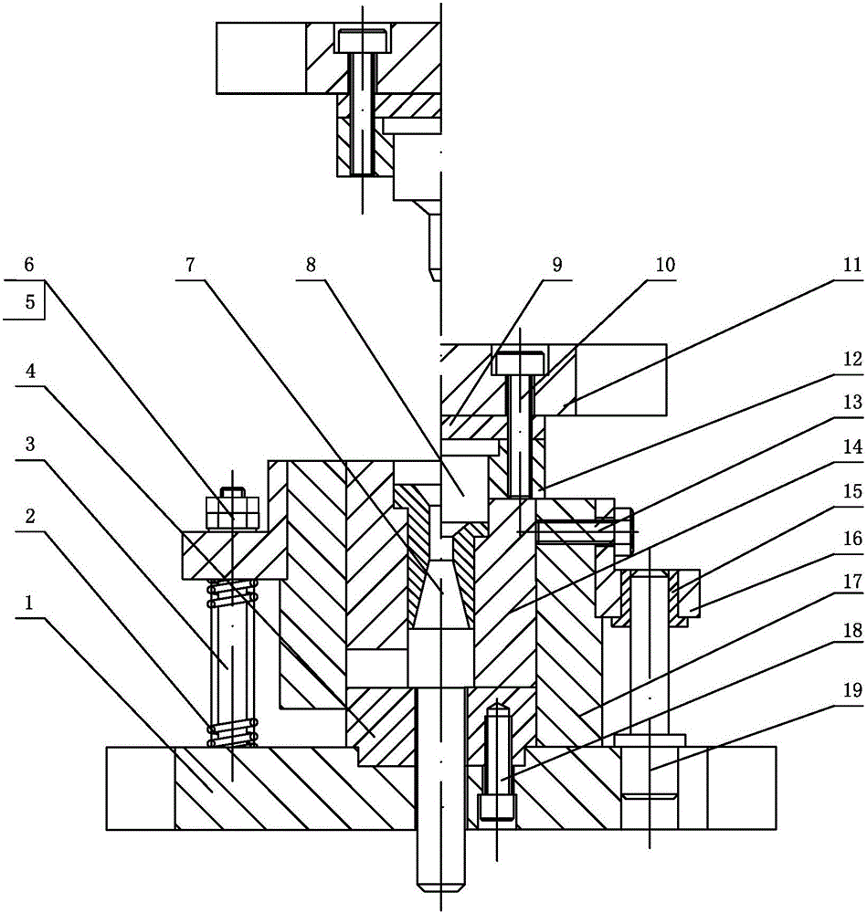
The invention discloses a forming technological method and a forming mould for an engine jet pipe, and relates to an extrusion forming method and a forming mould. The forming technological method and the forming mould are used for solving the problem that scouring burning loss on the neck of the spray pipe is caused by fuel gas as a result of poor high temperature resistance and poor high pressure resistance of parts of the engine jet pipe. The forming technological method comprises the following steps: I, preparing materials; II, preparing equipment; III, pre-forming; IV, sintering; V, carrying out hot extrusion forming; VI, carrying out quenching treatment; VII, carrying out low-temperature tempering; VIII, finish machining; and IX, phosphating. According to the forming mould, a cushion block is mounted in a groove of a lower mould base, wherein the lower mould base is connected with the cushion block; a reinforcing mould sleeve is mounted on the lower mould base; a return plate is clamped on a limiting table shoulder of the reinforcing mould sleeve; a plurality of return rods and a plurality of guide posts are separately arranged between the reinforcing mould sleeve and the lower mould base; a plurality of guide sleeves are mounted on the reinforcing mould sleeve in a plug-in manner; a concave mould is mounted in the reinforcing mould sleeve; a lower core mould is mounted in the concave mould; an upper core mould is clamped in a step hole of a clamping plate; and an upper molding board, a base plate and the clamping plate are sequentially arranged from top to bottom. The forming technological method and the forming mould are used for spray pipe extrusion forming.

Description

technical field [0001] The invention relates to a forming process method and a forming die, in particular to a forming process method and a forming die for an engine nozzle. Background technique [0002] When the ammunition engine is working, under the action of high temperature and high pressure, the burning damage caused by the propellant flame to the throat of the nozzle will have a great impact on the trajectory accuracy of the projectile trajectory. However, the high-quality carbon structural steel engine nozzle parts processed by the original machine cannot meet the performance requirements of the nozzle parts through many tests. In particular, it cannot satisfy the problem of high temperature resistance and high pressure performance of the engine nozzle parts, which cause the erosion and burning of the nozzle throat by the gas. Contents of the invention [0003] The purpose of the present invention is to solve the problem that the parts of the nozzle of the engine ...

Claims


Application Information

Patent Timeline
Patent Type & Authority Applications(China)
IPC IPC(8): B22F5/10B22F3/20B22F3/03B22F1/00C21D9/08C21D1/18
CPCC21D1/18C21D9/085B22F3/03B22F3/20B22F5/106B22F2998/10B22F2003/208B22F1/142B22F2003/242B22F2003/248B22F3/10B22F3/02
Inventor 贾连颖刘忠柏董延斌郭楠男
Owner HARBIN JIANCHENG GRP
Why Eureka
Try Eureka