Ultraviolet ray and infrared ray shielding glass capable of being subsequently processed

A technology for shielding glass and ultraviolet rays, applied in the field of special glass, can solve problems such as damage, damage to leather, furniture, artwork, accelerated skin aging, etc., and achieve the effect of low ultraviolet transmittance, avoiding film defects, and relieving internal stress.

Inactive Publication Date: 2016-08-24
BEIJING JINJING WISDOM CO LTD
View PDF4 Cites 3 Cited by
  • Summary
  • Abstract
  • Description
  • Claims
  • Application Information

AI Technical Summary

Problems solved by technology

[0004] However, the double-silver and triple-silver film layers are softer than the single silver film layer of the same material. In this way, simply increasing the number of Ag layers and dielectric layers will not only affect the appearance color and angle chromatic aberration of the product, but also cause heat loss. A series of issues of stability, mechanical durability and chemical durability
Therefore, without a specially designed film layer, it can only be coated on the surface of tempered glass by steel first and then plated, which greatly affects the production efficiency, and this film layer cannot be coated on the surface of curved steel glass.
[0005] At the same time, although the existing Low-E glass film layer design can block the transmission of most ultraviolet rays with a wavelength below 320nm, it does not have a good shielding effect on long-wave ultraviolet rays with a wavelength of 320-400nm.
The long-term accumulation of ultraviolet rays in this band will cause accelerated aging and serious damage to people's skin, as well as discoloration and damage of leather, furniture, and artwork

Method used


Image

  • Ultraviolet ray and infrared ray shielding glass capable of being subsequently processed
  • Ultraviolet ray and infrared ray shielding glass capable of being subsequently processed
  • Ultraviolet ray and infrared ray shielding glass capable of being subsequently processed

Examples


Embodiment Construction

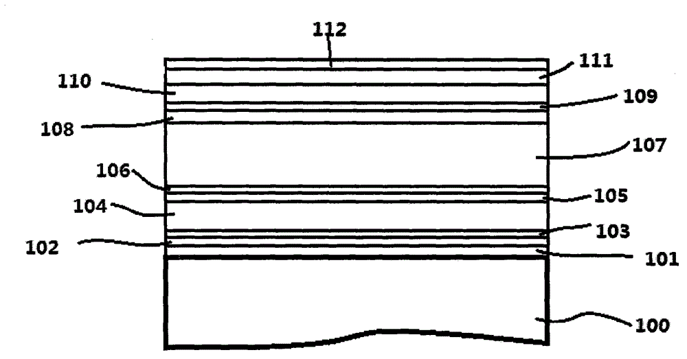
[0039] The following is the film system structure of an application example of the ultraviolet and infrared shielding glass that can be processed later provided by the present invention:

[0040] Glass substrate / ZnSnOx / ZnO / Ag / Ti / ZnO / ZnSnOx / ZnO / Ag / Ti / ZnO / ZnSnOx / ZnO / Ag / Ti / ZnO / ZnSnOx / CeO 2 / TiO 2 .

[0041] Wherein, the first oxide layer is a composite layer of ZnSnOx and ZnO with a thickness of 42-46nm, and transitions in a gradient growth manner.

[0042] The thickness of the first infrared reflective Ag layer is 11 nm.

[0043] The first barrier layer is a Ti layer with an areal density of 1.1 μg / cm 2 .

[0044] The second oxide layer is a composite layer of ZnSnOx and ZnO with a thickness of 70-75nm, and the two layers of ZnO and ZnSnOx are transitioned in the manner of gradient growth.

[0045]The thickness of the second infrared reflective Ag layer is 13 nm.

[0046] The second barrier layer is a Ti layer with an areal density of 1.2 μg / cm 2 .

[0047] The third oxi...


PUM

PropertyMeasurementUnit
thicknessaaaaaaaaaa
thicknessaaaaaaaaaa
thicknessaaaaaaaaaa

Abstract

The invention provides ultraviolet ray and infrared ray shielding glass capable of being subsequently processed through special design. The ultraviolet ray and infrared ray shielding glass is characterized in that a plurality of thin films composed of a first oxide layer 101 / first infrared reflecting layer 102 / first blocking layer 103 / second oxide layer 104 / second infrared reflecting layer 105 / second blocking layer 106 / third oxide layer 107 / third infrared reflecting layer 108 / third blocking layer 109 / fourth oxide layer 110 / ultraviolet blocking layer 111 / protection layer 112 is sedimented on one surface of glass through the magnetron sputtering coating technology. The ultraviolet ray and infrared ray shielding glass has the advantages of being high in visible light transmittance and extremely low in ultraviolet and infrared light transmittance, and is stable in optical performance, resistant to heat and weather and capable of achieving remote subsequent tempering, hot bending, doubling and the like, and a very good choice is provided for high-grade building glass.

Description

【Technical field】 [0001] The invention relates to the field of special glass, in particular to a kind of temperable coated glass with high transmittance to visible light and high shielding to infrared and ultraviolet light. 【Background technique】 [0002] Low-emissivity (also known as Low-E) glass is a kind of coated glass with very good energy-saving effect. Now it has been widely used in buildings, automobiles, and industrial fields such as refrigerators and microwave ovens. It is coated with a special film layer on the glass substrate, allowing short-wavelength energy, such as visible light and ultraviolet energy, to pass through the film layer, while reflecting long-wavelength energy, such as infrared energy, and ultimately reducing heating or cooling energy. Consumption effect. [0003] The structural design of this kind of coating is generally to add an infrared reflective Ag layer between the two dielectric layers, and the emissivity of the coated glass depends on th...

Claims


Application Information

Patent Timeline
Patent Type & Authority Applications(China)
IPC IPC(8): C03C17/36
Inventor 张欣季亚林
Owner BEIJING JINJING WISDOM CO LTD
Why Eureka
Try Eureka