Oil and gas field drilling waste mud treatment device

A waste mud and treatment device technology, applied in water/sludge/sewage treatment, sludge treatment through temperature control, dehydration/drying/thickened sludge treatment, etc. Problems such as too much material, to achieve the effect of low production cost, small footprint and high processing efficiency

Active Publication Date: 2018-07-27
商洛市海蓝科技有限公司 +1
View PDF6 Cites 0 Cited by
  • Summary
  • Abstract
  • Description
  • Claims
  • Application Information

AI Technical Summary

Problems solved by technology

[0007] The object of the present invention is to overcome the shortcomings in the above-mentioned prior art, and provide a treatment device for oil and gas field drilling waste mud, which overcomes the existing oilfield waste treatment methods that occupy a large area, have a lot of waste after treatment, and poor actual standards, Ineffective and other shortcomings, and effectively solve the problems of secondary pollution, high cost, and complicated operation in conventional treatment methods, realize the harmless treatment of drilling waste, and the disposal mixture meets the third-level standard of national soil quality; and the structure is simple , each component is highly integrated, the device occupies a small area, can be concentrated and continuous, and improves the processing efficiency

Method used


Image

  • Oil and gas field drilling waste mud treatment device
  • Oil and gas field drilling waste mud treatment device
  • Oil and gas field drilling waste mud treatment device

Examples


Embodiment Construction

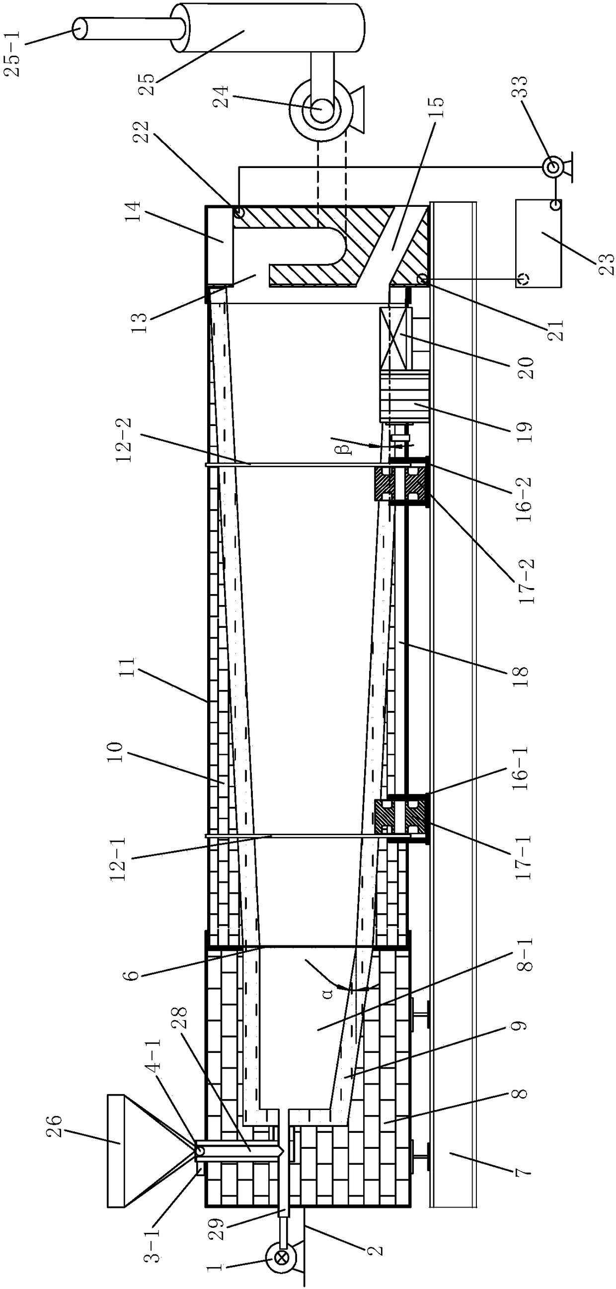
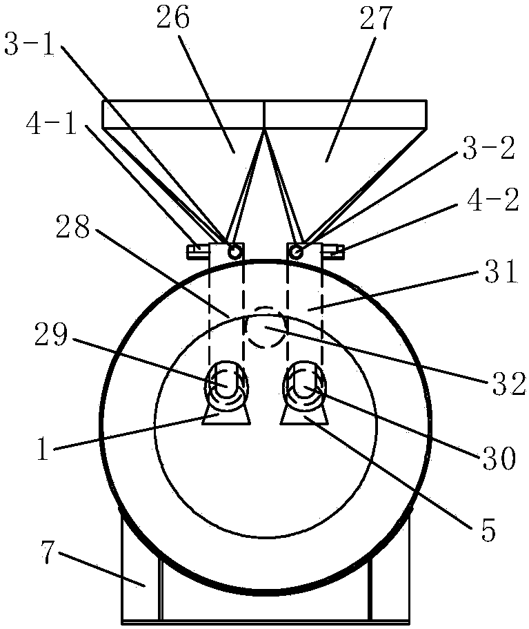
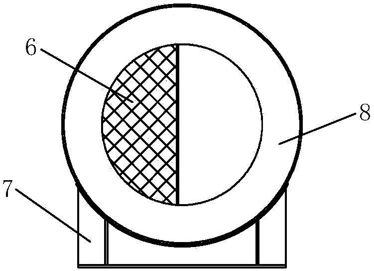
[0044] Such as figure 1 and figure 2 As shown, the present invention includes a kiln body, and the kiln body includes a kiln body head 8, a kiln body middle section 11 and a kiln body tail 14 arranged in sequence from front to back, and the kiln body middle section 11 is connected with the kiln body head 8 and the kiln body The tail parts 14 of the kiln body are all rotatably connected, and a rotary drive mechanism for driving the kiln body is arranged below the middle section 11 of the kiln body. The inner cavity of 11 communicates with the inner cavity of the kiln body tail 14 and the kiln head combustion chamber 8-1, and the front part of the kiln body head 8 is provided with a pulverized coal feeding pipe 28, a material feeding pipe 31, a pulverized coal The air inlet pipe 29 and the material air inlet pipe 30, the pulverized coal air inlet pipe 29 is located below the pulverized coal feeding pipe 28 and communicates with the lower end of the pulverized coal feeding pipe...


PUM


Abstract

The invention discloses an oil-gas field well drilling waste sludge treatment device. The oil-gas field well drilling waste sludge treatment device comprises a kiln. The kiln comprises a kiln head, a kiln middle portion and a kiln tail. The kiln middle portion is rotationally connected with the kiln head and the kiln tail respectively. A rotational driving mechanism is arranged below the kiln middle portion. A pulverized coal feed pipe, a material feed pipe, a pulverized coal air inlet pipe and a material air inlet pipe are arranged on the front portion of the kiln head. A pulverized coal hopper is mounted at the upper end of the pulverized coal feed pipe. A material hopper is mounted at the upper end of the material feed pipe. A pulverized coal blower is connected to an air inlet of the pulverized coal air inlet pipe. A material blower is connected to an air inlet of the material air inlet pipe. A lighting-up tuyere is arranged on the kiln head. A discharge outlet is arranged at the bottom of the kiln tail. An exhaust outlet is arranged on the upper portion of the kiln tail. A gas purification system is connected to the exhaust outlet. The oil-gas field well drilling waste sludge treatment device has the advantages that harmless treatment of well drilling waste materials is realized, treated mixtures meet three-level standards of natural soil quality, components are highly integrated, occupied area of the device is small, concentration and continuation in operation are achieved, and treatment efficiency is high.

Description

technical field [0001] The invention belongs to the technical field of oil and gas field drilling engineering, and in particular relates to a treatment device for oil and gas field drilling waste mud. Background technique [0002] Drilling waste mud in oil and gas fields is a multiple stable colloidal suspension system containing clay, weighted materials, various chemical mud treatment agents, a certain amount of dirty oil and drilling cuttings. The hydrocarbons, salts, various polymers, sulfonates, and certain metal ions contained in it are extremely harmful to the environment. If they are not treated, they will definitely cause serious pollution to the surrounding environment of oil and gas fields and groundwater. With the strengthening of people's awareness of environmental protection, the hazards and impacts of oil and gas field drilling waste mud on the environment have attracted much attention, and many countries have listed it as an important project of environmental ...

Claims


Application Information

Patent Timeline
Patent Type & Authority Patents(China)
IPC IPC(8): E21B41/00F23G7/08F23G5/22C02F11/18C02F11/12
CPCC02F11/12C02F11/18C02F2303/06E21B41/0071F23G5/22F23G7/08
Inventor 康朝权
Owner 商洛市海蓝科技有限公司
Why Eureka
Try Eureka