A kind of economizer that changes the area and flow mode to increase the flue gas temperature at the scr inlet

A flow mode and economizer technology, applied in feed water heaters, lighting and heating equipment, preheating, etc., can solve problems such as low denitrification efficiency, incomplete denitrification, and low flue gas reaction temperature

Active Publication Date: 2018-05-22
NORTH CHINA ELECTRIC POWER UNIV (BAODING)
View PDF4 Cites 0 Cited by
  • Summary
  • Abstract
  • Description
  • Claims
  • Application Information

AI Technical Summary

Problems solved by technology

However, during the low peak period of electricity consumption, the power plant boiler operates under low load, the reaction temperature of the flue gas in the system is low, and the activity of the catalyst is reduced, resulting in a low denitrification efficiency
The denitrification system will stop running until the inlet flue gas temperature is lower than the lower limit of the system’s operating temperature, but the catalyst is still being washed by the flue gas and will continue to wear, which not only reduces the service life of the catalyst, but also fails to complete the denitrification. The purpose is to make the power station unable to meet the emission standards stipulated by the state

Method used


Image

  • A kind of economizer that changes the area and flow mode to increase the flue gas temperature at the scr inlet
  • A kind of economizer that changes the area and flow mode to increase the flue gas temperature at the scr inlet

Examples


Embodiment Construction

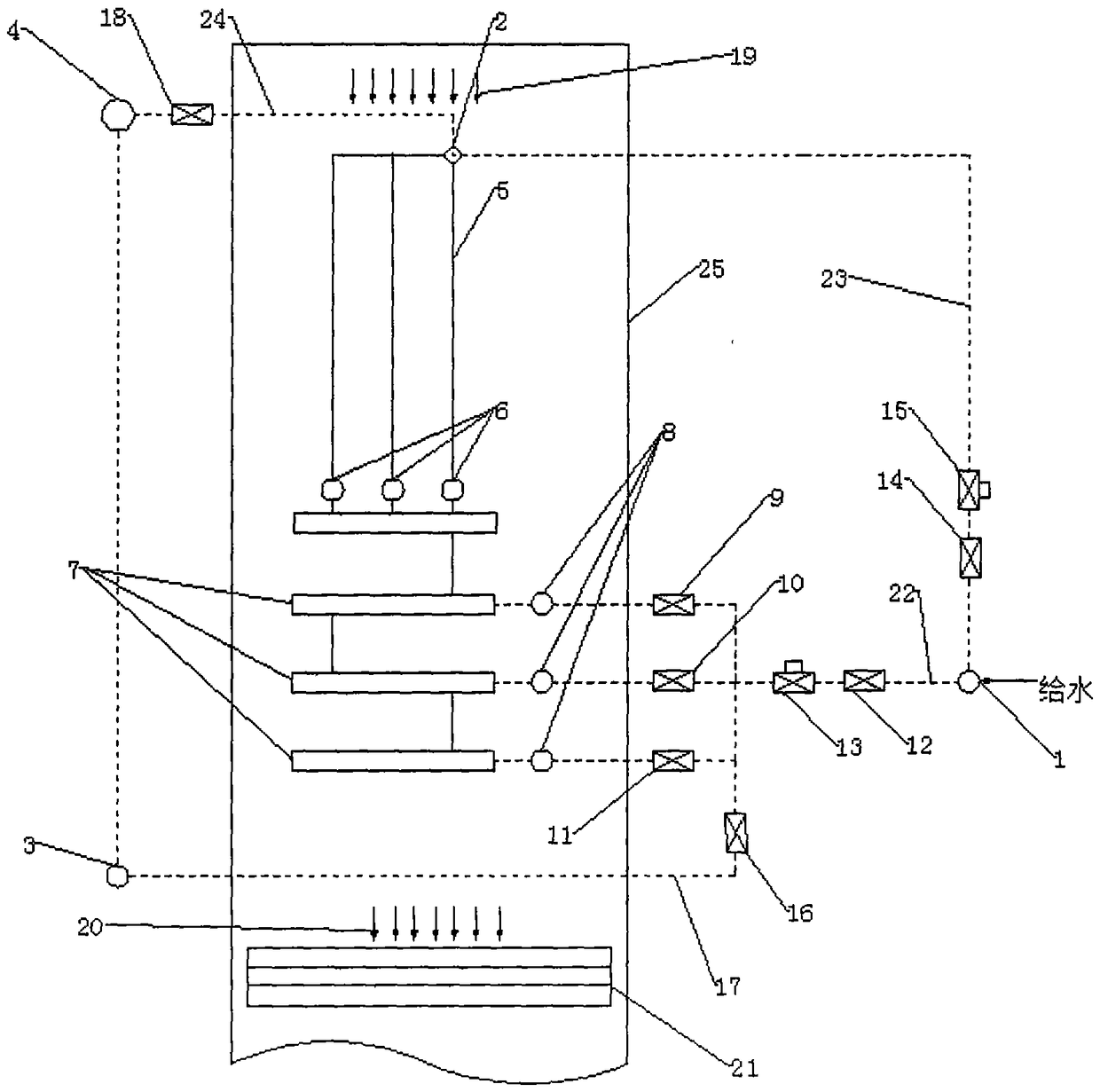
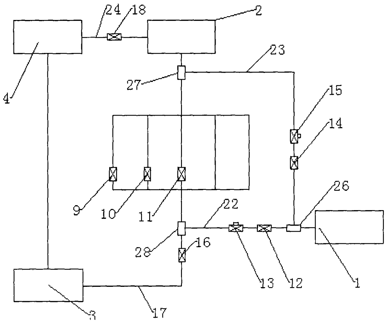
[0012] The present invention includes specific implementation steps.

[0013] Such as figure 1 with figure 2 As shown, an economizer that changes the area and flow mode to increase the flue temperature at the SCR inlet, including the furnace flue shell 25, the economizer outlet A header 2 located in the furnace flue shell 25, and the economizer A group of economizer suspension pipes 5 connected to outlet A header 2, an intermediate header 6 of economizer group A connected to each economizer suspension pipe 5, and an intermediate header 6 of economizer group A A group of economizer serpentine pipes 7, the middle group B header of the economizer connected to the economizer serpentine pipes 7, and the SCR reactor 21 connected to the bottom of the furnace flue shell 25; the economizer A first branch pipe 22 is provided between the inlet header 1 of the economizer group B and the middle header 8 of the economizer group B, and the first branch pipe 22 is provided with a first bra...


PUM


Abstract

The invention discloses an economizer which changes the area and flow mode to increase the smoke temperature at the inlet of the SCR. A bypass is arranged on the water supply pipeline connected to the inlet header of the economizer. The bypass is divided into two branches, the first The branch is connected with the serpentine header of the economizer, and the second branch is directly connected with the outlet header of the economizer. In the two branch pipes, a shut-off valve and a flow regulating valve are respectively arranged in sequence along the direction of fluid flow. . Adopting the present invention is to adjust the heating area of ​​the economizer group by adjusting the first branch valve, thereby reducing the heat exchange of the economizer system to control the flue gas temperature at the outlet of the economizer; adjusting the second branch valve to change The flow mode of flue gas and water, so that the low-load working conditions that could not meet the SCR commissioning conditions can meet the temperature requirements of SCR commissioning, effectively improving the continuous operation time of the SCR denitrification system of the power plant, and the SCR denitrification system under low-load conditions. The increase of the flue gas temperature in the system leads to the increase of the activity of the SCR catalyst, which enhances the denitrification capability of the SCR system.

Description

technical field [0001] The invention relates to the field of flue gas denitrification of power station boilers, in particular to an economizer which improves the flue gas temperature at the SCR inlet by changing the area and flow mode. Background technique [0002] Selective Catalytic Reduction (SCR) denitration technology has a high denitration rate, NH 3 The escape rate is low, the operation is stable, and the maintenance is convenient. It has become a relatively mature mainstream technology for denitration in power plants at home and abroad. NO accounts for about 95% of nitrogen oxides, NO 2 accounts for about 5%, and also contains a small amount of N 2 O, when these gases are discharged into the atmosphere, they will produce acid rain, photochemical smog, ozone layer depletion and other hazards, and are one of the important sources of environmental air pollution. SCR technology is under the action of catalyst to generate harmless N 2 and H 2 O; At the same time, it ...

Claims


Application Information

Patent Timeline
Patent Type & Authority Patents(China)
IPC IPC(8): F22D1/02F22D1/12
Inventor 高正阳杨朋飞高舒慈吕少昆陈嵩涛吉硕
Owner NORTH CHINA ELECTRIC POWER UNIV (BAODING)
Why Eureka
Try Eureka