Method and device for visually identifying artificial intelligent machine under common and special environments

A machine vision and artificial intelligence technology, applied in measurement devices, instruments, photogrammetry/video measurement, etc., can solve the problems of limited use environment, slow speed, and large computational load of dual cameras, and achieves improved clarity, improved The effect of recognition accuracy

Active Publication Date: 2016-08-24
QINGDAO TECHNOLOGICAL UNIVERSITY +2
View PDF5 Cites 4 Cited by
  • Summary
  • Abstract
  • Description
  • Claims
  • Application Information

AI Technical Summary

Problems solved by technology

This type of method is slow because of the existence of the scanning structure; or, because of the use of general-purpose equipment, such as a projector, it is not suitable for special environments such as high radiation, high temperature, and high pressure; or, the computational load of dual cameras is relatively large. ; or, because of the use of holographic interferometry, it is only suitable for laboratories, limiting the use of the environment

Method used


Image

  • Method and device for visually identifying artificial intelligent machine under common and special environments
  • Method and device for visually identifying artificial intelligent machine under common and special environments
  • Method and device for visually identifying artificial intelligent machine under common and special environments

Examples


Embodiment Construction

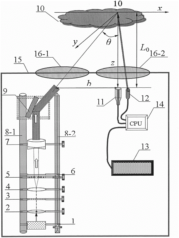
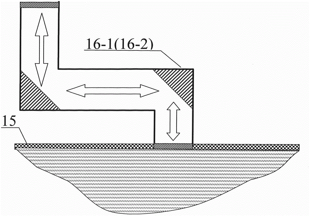
[0083] The artificial intelligence machine vision recognition method for ordinary and special environments of the present invention is to utilize the laser device 1, the beam shaping system 2, the rectangular grating 3, and the monochromatic Fourier transform lens that are sequentially arranged on the precision screw 8-1 and the precision guide rail 8-2 along the optical path 4. The sinusoidal structured light output system composed of spectrum selector 5, wave plate 6, monochromatic variable magnification lens 7, and high-speed vibrating mirror 9 projects sinusoidal structured light to the target 10 to be identified; the computer 14 and the telecentric lens connected thereto and a high-speed CCD (CMOS) 11, a laser ranging system 12, and an internal environment control system 13 to visually collect and identify the target 10 to be identified; through the built-in sinusoidal structured light output system and the protective shell 15 of the visually collected and recognized system...


PUM


Abstract

The invention relates to a method and a device for visually identifying an artificial intelligent machine under common and special environments. The invention aims to solve the problem that the prior art is not suitable for multi-field measurement. A light output system is composed of a laser (1), a beam shaping system (2), a rectangular raster (3), a monochrome Fourier transform lens (4), a frequency spectrum selector (5), a wave plate (6), a monochrome multiplying power lens (7) and a high-speed scan mirror (9) which are successively arranged on a precision lead screw (8-1) and a precision guide rail (8-2) in turn along the light path; the light output system is utilized to project sine structured light; a visual collecting identifying system is used for visually collecting and identifying a to-be-identified target (10); the visual collecting identifying system is composed of a computer (14), a telecentric lens connected with the computer (14), a high speed CCD or CMOS (11), a laser ranging system (12) and an internal environment control system (13); a protecting shell (15), in which the light output system and the visual collecting identifying system are arranged, is provided with a radiation protection window used for performing radiation protection on the light output system and the visual collecting identifying system. The device is specifically fit for the continuous output of sine structured light under large-field range measurement from the near to the distant and has the advantage of mode recognition for static, low-speed and high-speed moving objects at different distances and with different characteristics.

Description

technical field [0001] The invention relates to a machine vision recognition method, in particular to an artificial intelligence machine vision recognition method and device for common and special environments. Background technique [0002] At present, artificial intelligence machine vision recognition methods mainly realize pattern recognition by directly shooting images and combining graphic image recognition algorithms. For specific objects, specific software algorithms are used for identification; such methods and technologies are also mainly applied to specific and single identification objects. For example: integrity recognition of tablets and capsules in medicine; liquid level recognition of plastic bottles, beverages, alcohol, etc.; edge detection and recognition fields such as image edge integrity recognition in the printing and dyeing industry; others such as: ports, airports, railway stations, Fields such as import and export goods detection generally require man...

Claims


Application Information

Patent Timeline
Patent Type & Authority Applications(China)
IPC IPC(8): G01C11/00G06T7/00
Inventor 李宏升岳军邓剑平陈冰泉李延娥任旭升李县洛滕霖王涛宋立梅陈勇张敏廖延彪
Owner QINGDAO TECHNOLOGICAL UNIVERSITY
Why Eureka
Try Eureka