Visualized testing device for cavitation-cavitation erosion relation measurement

A technology of cavitation cavitation and test equipment, which is applied in the direction of measuring equipment, testing wear resistance, instruments, etc., can solve the problem that cavitation cannot be measured visually and quantitatively, and it is difficult to observe the generation area and dynamic characteristics of cavitation groups etc. to achieve the effects of easy processing and acquisition, change of saturated vapor pressure, and high measurement accuracy

Inactive Publication Date: 2016-08-24
JIANGSU UNIV
View PDF8 Cites 16 Cited by
  • Summary
  • Abstract
  • Description
  • Claims
  • Application Information

AI Technical Summary

Problems solved by technology

These experimental facilities can only observe the cavitation on the surface of the material after a period of cavitation, and it is difficult to observe the generation area and dynamic characteristics of the cavitation group during the cavitation process; in addition, in order to ensure the continui

Method used


Image

  • Visualized testing device for cavitation-cavitation erosion relation measurement
  • Visualized testing device for cavitation-cavitation erosion relation measurement

Examples


Embodiment Construction

[0028] The invention will be described in further detail below in conjunction with the accompanying drawings.

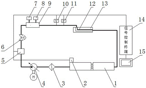
[0029] The structure of a visual test device for cavitation cavitation relationship measurement of the present invention is as follows: figure 1 As shown in the figure, P represents the pressure transmission unit, that is, the pressure sensor 11, V represents the flow transmission unit, that is, the flow sensor 10, and the thick solid line represents the pipeline. The test device includes fuel supply system, reaction system and measurement system.

[0030] The fuel supply system is used to ensure the self-circulation flow of fuel. The fuel supply system includes fuel tank 1, diesel filter 3, pump station 4, oil pressure regulating valve 5, adjustable butterfly valve 6, compressor 7, vacuum pump 8 and buffer section 9 The fuel tank 1 is provided with a heating tile 2 for opening and closing according to the test requirements, and the fuel is extracted from the fuel t...


PUM


Abstract

The invention discloses a visualized testing device for cavitation-cavitation erosion relation measurement. The device comprises a fuel oil supply system, a reaction system and a measurement system, the fuel oil supply system comprises a fuel tank, a heating device, a diesel filter, a pump station, an oil pressure adjusting valve, an adjustable butterfly valve, a buffer section, a compressor and a vacuum pump; the reaction system comprises a test section and a metal foil piece; the measurement system comprises a pressure sensor, a flow sensor, a signal control terminal and a computer. The visualized testing device has the advantages that the structure is simple, the device runs stably, cavitation erosion intensity is continuously adjustable, test operation is simple, the induced cavitation performance effect of the test section is good, and the generation areas of vacuole clusters adjacent to the test section and cavitation erosion characteristics on the metal foil piece are easy to observe.

Description

technical field [0001] The patent of the present invention relates to the technical field of hydraulic cavitation cavitation erosion. In particular, it refers to a visual test device for cavitation and cavitation erosion relationship measurement. Background technique [0002] Cavitation erosion is the surface damage caused by the formation and collapse of cavitation bubbles in the liquid medium due to local pressure changes under certain ambient temperature conditions, and the material is continuously impacted by high-pressure, high-speed micro-jet. For a long time, cavitation has seriously affected the performance and service life of drainage structures, hydraulic machinery (water pumps, turbines, gates), and ship propellers. Cavitation involves many fields, such as aerospace, national defense, navigation, chemical industry, atomic energy, even biology and medicine, etc., and it has become one of the problems encountered in these fields. So far, the theory about cavitatio...

Claims


Application Information

Patent Timeline
IPC IPC(8): G01N3/56
CPCG01N3/567
Inventor 何志霞张鑫王谦张文权
Owner JIANGSU UNIV
Why Eureka
Try Eureka