
Vehicle laser radar distance and velocity measurement method

A vehicle-mounted laser radar and speed measurement technology, which is applied in the field of laser radar, can solve the problems of increasing the maximum speed, etc., and achieve the effects of increasing range, reducing equipment cost, and improving use efficiency

Inactive Publication Date: 2016-08-24
WUHAN UNIV OF SCI & TECH
View PDF1 Cites 8 Cited by
  • Summary
  • Abstract
  • Description
  • Claims
  • Application Information

AI Technical Summary

Problems solved by technology

Taking into account the actual speeding situation, the maximum speed will be further increased
Also, when the vehicle in front moves away from the vehicle at a certain speed, its speed limit can be considered as -120km / h under statutory circumstances (the negative sign indicates the direction, that is, away from the vehicle), which is also unmeasured by the method of the Toyota Central Research Institute.

Method used


Image

  • Vehicle laser radar distance and velocity measurement method
  • Vehicle laser radar distance and velocity measurement method
  • Vehicle laser radar distance and velocity measurement method

Examples


example 1

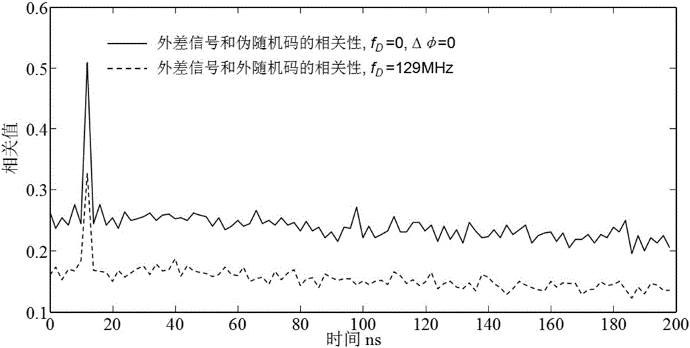
[0095] The modulation code width is set to 2ns, the signal length is 770ns, and the Doppler frequency of the received signal is 129MHz. Calculate the correlation function between the heterodyne signal and the modulation code, and observe that the peak value of the correlation function is affected by the Doppler frequency modulation. The results are as follows image 3 shown by the dotted line. In the case of the same signal peak power, the peak value of the correlation function output by direct detection (the received signal is not modulated by Doppler frequency) is represented by the solid line. Because the modulation effect of Doppler frequency reduces the peak value of the output correlation function, but it is noted that the coherent detection local signal has an amplification effect on the received signal, and the actual detection performance is better than that of direct detection.

example 2

[0097] The distance detection performance is mainly determined by the peak value of the correlation function. In this embodiment, the difference between the largest peak value and the second peak value is investigated. The larger the difference value, the better the anti-noise performance. In addition, it can be seen from formula (9) that the instantaneous power of the output heterodyne signal is affected by the phase. In this embodiment, when the phase changes from 0 to 2π, the change of the peak value and the sub-peak of the correlation function, the results are as follows Figure 4 shown. Four typical values ​​of 16MHz, 60MHz, 129MHz and 209MHz are selected for the Doppler frequency of the received signal, all of which are within the range of 15.5-209MHz. The results show that the difference between the maximum peak value and the secondary peak value is almost not affected by the phase, indicating that the randomness of the arrival time of the received signal does not affe...

example 3

[0099] This embodiment tests the feasibility of using the frequency spectrum analysis method for non-equally spaced sampling signals to analyze the frequency of Doppler signals. Also select four typical values ​​of 16MHz, 60MHz, 129MHz and 209MHz, sample the signals of the four frequencies according to the sampling period of the modulation code width, correct the sampled data according to the formula (8), and then use the classic fast Fourier transform algorithm Perform Fourier analysis on the amplitude-corrected data to find the frequency of the Doppler signal. The analysis results are as follows: Image 6 shown.

[0100] Function and effect of embodiment

[0101] According to the vehicle-mounted lidar distance and speed measurement method involved in this embodiment, the narrow-linewidth single-frequency laser is a pulse sequence, which can improve the detection stability of the lidar and meet the laser safety use standards; on the one hand, the use of a single photoelectri...


PUM


Abstract

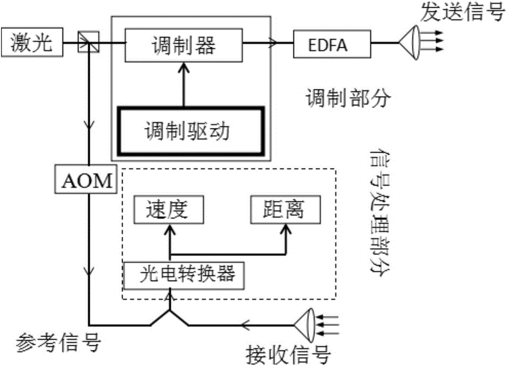
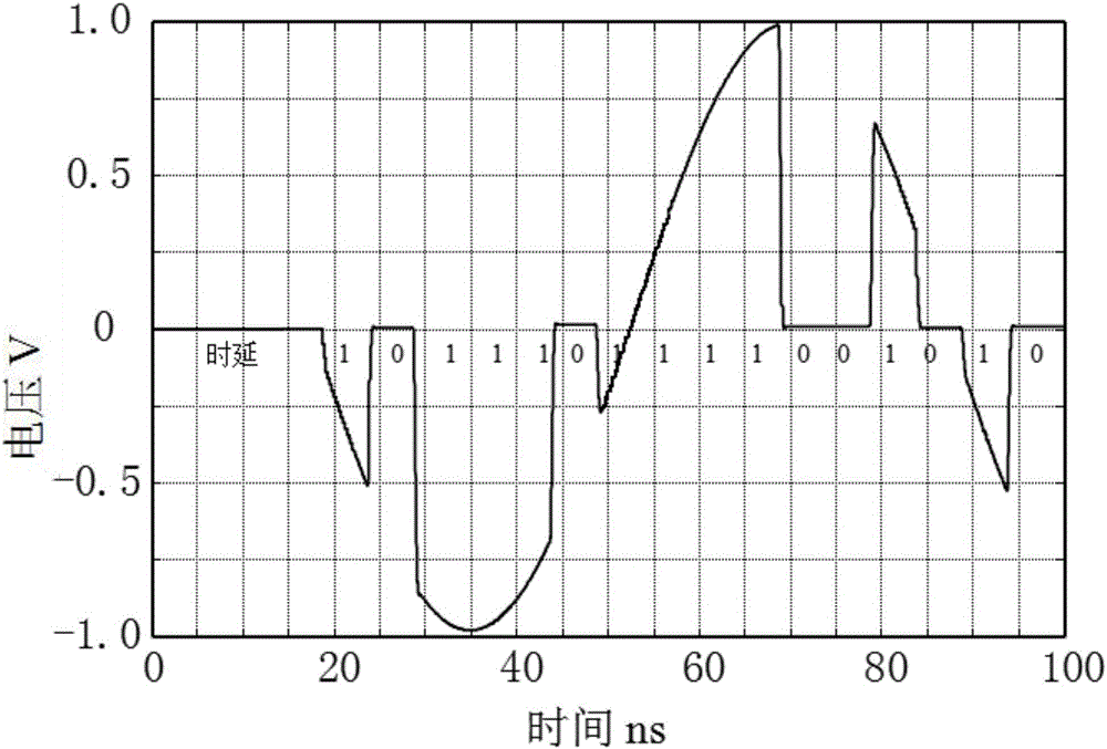
The invention provides a vehicle laser radar distance and velocity measurement method, which is characterized by comprising a first step of driving, via a laser drive circuit, a laser to generate a narrow linewidth single frequency laser with continuous amplitude; a second step of, outputting, via an optical splitter, measurement light in the narrow linewidth single frequency laser outputted by the laser to an electrooptical modulator, and allowing the remaining reference light to pass through an acoustic optical modulator to generate a frequency offset for use locally as a reference signal; a third step of generating, by a local pulse generating circuit, a pseudo-random code, and obtaining a probe signal of a laser radar; a fourth step of enabling the probe signal to pass through an erbium-doped optical fiber amplifier so that the optical signal peak power can be amplified to 100W order or greater to form an amplified optical signal; a fifth step of mixing the amplified optical signal with the reference signal to output a heterodyne signal; a sixth step of calculating a correlation function of the heterodyne signal and a modulation code, so as to obtain the distance of a target; and a seventh step of analyzing unequal interval data acquired through heterodyne signal sampling, and thus obtaining the speed of the moving target.

Description

technical field [0001] The invention relates to the technical field of laser radar, in particular to a method for measuring distance and speed of vehicle-mounted laser radar. Background technique [0002] In the automotive industry, millimeter-wave radar uses frequency-modulated continuous waves to realize the simultaneous detection of the distance and speed of road targets. This technology has been widely used in assisted driving and automatic driving. However, the spatial resolution of millimeter-wave radar is poor, and its ability to image the road environment is insufficient. For example, in a multi-target environment, it is easy to identify two targets as a single target, resulting in wrong judgments at the decision-making end and potentially causing traffic accidents. In order to improve the spatial resolution of target detection, it is the best choice to choose laser as the emission light source, because the laser has excellent collimation effect. Although lidar has...

Claims


Application Information

Patent Timeline
IPC IPC(8): G01S17/32G01S17/58
CPCG01S17/32G01S17/58
Inventor 毛雪松王瑞东
Owner WUHAN UNIV OF SCI & TECH
Learn More