Directional emission scintillator controlled by surface plasmon
A surface plasmon and scintillator technology, used in the field of nuclear radiation detection, can solve the problem that metal particles cannot be directly applied, and achieve the effects of improved luminous intensity, high sensitivity and signal-to-noise ratio
- Summary
- Abstract
- Description
- Claims
- Application Information
AI Technical Summary
Problems solved by technology
Method used
Image

Examples
Embodiment 1
[0026] The selected substrate in this embodiment is a silicon wafer, the period of the metallic silver columnar array on the silicon wafer is 300 nm, the diameter of the metallic silver is 140 nm, and the height of the metallic silver is 90 nm. The plastic scintillator is 1 micron thick.
[0027] The sample preparation process is as follows:
[0028] 1. Preparation of metallic silver columnar array:
[0029] (1) Soft template preparation. Perfluorooctyltrichlorosilane was prepared on the hard template by the liquid phase method, so that the surface of the hard template used for nanoimprinting and the surface of the inner wall of the microstructure self-assembled to form a single-molecule anti-adhesive layer, which has a low The free energy is conducive to demoulding; the PDMS (60wt%) diluted in toluene is spin-coated on the surface of the nanoimprint template after anti-sticking treatment, then baked at 120 degrees Celsius for 20 minutes, and demoulding when it is lowered to...
Embodiment 2
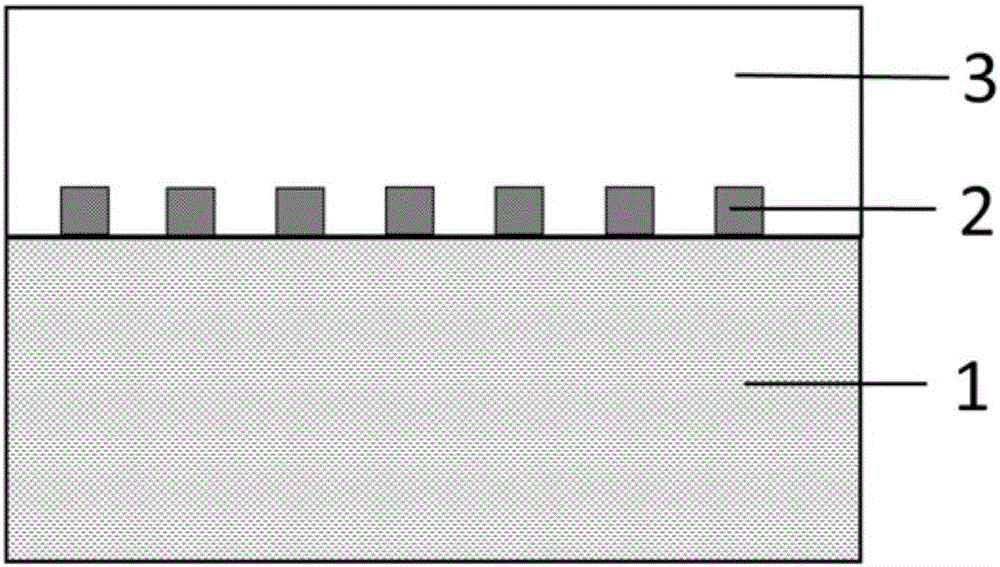
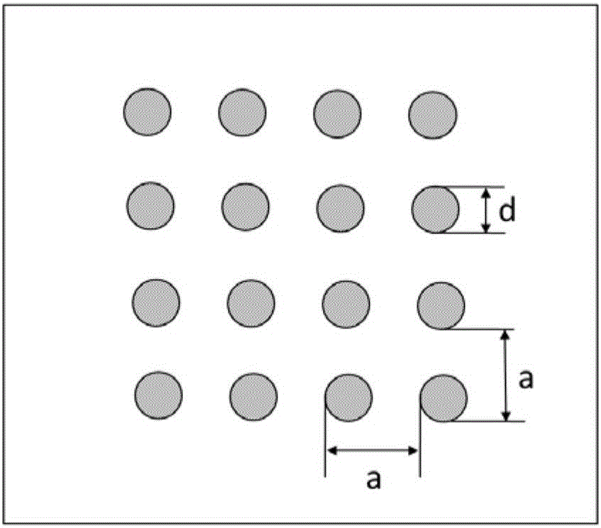
[0044] The directional emission scintillator controlled by surface plasmons includes a silicon chip as a base layer, a metal periodic array structure arranged on the base layer, and a plastic scintillator arranged on the metal periodic array structure. The metal periodic array is an array formed by columnar metal aluminum units distributed periodically in a triangular structure. The distance between the adjacent metal aluminum units is 280nm, the diameter of the metal aluminum unit is 0.4 of the distance between the adjacent metal aluminum units, and the height of the metal aluminum unit is 80nm. The plastic scintillator covers the metal periodic array structure with a height of 1 μm. The plastic scintillator is a plastic matrix doped with a luminescent agent and a wave-shifting agent. In the embodiment, the plastic matrix is polymethylstyrene, and the luminescent agent is a couplet three Benzene, the wave shifting agent is BBO.
Embodiment 3
[0046] The directional emission scintillator controlled by surface plasmons includes quartz glass as a base layer, a metal periodic array structure arranged on the base layer, and a plastic scintillator arranged on the metal periodic array structure. The metal periodic array is an array formed by columnar metal silver units distributed periodically in a square shape. The distance between adjacent metal silver units is 300nm, the diameter of the metal silver unit is 0.5 of the distance between adjacent metal silver units, and the height of the metal silver unit is 90nm. The plastic scintillator is covered on the metal periodic array structure with a height of 2 μm. The plastic scintillator is a plastic matrix doped with a luminescent agent. In the embodiment, the plastic matrix is polymethyl methacrylate, and the luminescent agent is PBD.
PUM
| Property | Measurement | Unit |
|---|---|---|
| Height | aaaaa | aaaaa |
| Diameter | aaaaa | aaaaa |
| Height | aaaaa | aaaaa |
Abstract
Description
Claims
Application Information
 - Generate Ideas
- Intellectual Property
- Life Sciences
- Materials
- Tech Scout
- Unparalleled Data Quality
- Higher Quality Content
- 60% Fewer Hallucinations
Browse by: Latest US Patents, China's latest patents, Technical Efficacy Thesaurus, Application Domain, Technology Topic, Popular Technical Reports.
© 2025 PatSnap. All rights reserved.Legal|Privacy policy|Modern Slavery Act Transparency Statement|Sitemap|About US| Contact US: help@patsnap.com