Waste cutting fluid treatment process

A waste cutting fluid and treatment process technology, which is applied in the field of waste cutting fluid treatment process, can solve the problems of high operating pressure, high operating cost, and complicated process, and achieve the effects of low treatment cost, good effect, and stable effluent quality

Inactive Publication Date: 2016-08-31
TIANJIN HIPURE MEMBRANE TECH CO LTD
View PDF3 Cites 7 Cited by
  • Summary
  • Abstract
  • Description
  • Claims
  • Application Information

AI Technical Summary

Problems solved by technology

Existing membrane technology uses vibrating nanofiltration membrane and reverse osmosis membrane to treat waste cutting fluid. The waste cutting fl

Method used


Image

  • Waste cutting fluid treatment process

Examples


Embodiment Construction

[0020] In order to further understand the content of the invention, characteristics and effects of the present invention, the following examples are described in detail as follows:

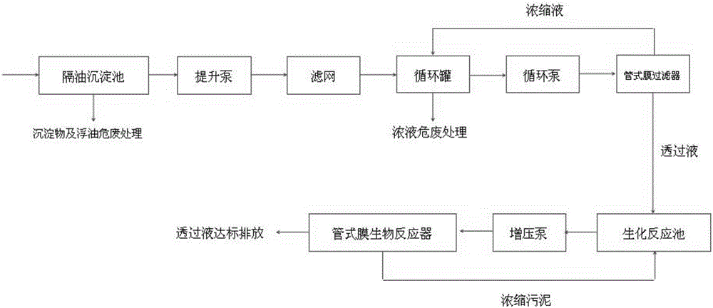
[0021] see figure 1 , the process of the present invention includes the following flow process,

[0022] 1) The waste cutting fluid enters the oil-separating sedimentation tank for sedimentation and oil-separation. Large and heavy metal particles sink to the bottom of the tank, and lighter oil floats on the liquid surface and is removed separately;

[0023] 2) The effluent from the oil-separating sedimentation tank is filtered by the lift pump through the filter to remove the smaller metal particles in the cutting fluid, and then enters the circulation tank. The mesh size of the filter is 0.1-1mm;

[0024] 3) The effluent of the circulation tank is lifted by the circulation pump and enters the tubular membrane filter for oil removal and filtration. The permeate of the tubular membrane filter ente...


PUM


Abstract

The invention belongs to the technical field of cutting fluid, in particular to a waste cutting fluid treatment process. The process comprises the following steps that 1, waste cutting fluid enters a grease-separation sedimentation tank; 2, after being filtered through a filter screen, outlet water of the grease-separation sedimentation tank enters a circulation tank; 3, outlet water of the circulation tank enters a tubular membrane filter, permeation liquid enters a biochemical reaction tank, concentrated liquor flows back into the circulation tank, and after being concentrated, the concentrated liquor is drained for hazardous waste treatment; 4, outlet water of the biochemical reaction tank enters a tubular membrane bioreactor for mud-water separation, the permeation liquid is drained, and the concentrated liquor flows back into the biochemical reaction tank. The waste cutting fluid treatment process is simple in process, convenient to operate and high in quality of outlet water; according to the process, the tubular membrane technology is adopted, and the process is easy to operate, reliable in operation, high in treatment efficiency, stable in quality of outlet water and low in treatment cost.

Description

technical field [0001] The invention belongs to the technical field of cutting fluid, and in particular relates to a process for treating waste cutting fluid. Background technique [0002] Cutting fluid is an industrial liquid used to cool and lubricate cutting tools and workpieces during metal cutting and grinding. Performance, lubricating performance, anti-rust performance, degreasing and cleaning function, anti-corrosion function, easy to dilute and other characteristics. [0003] Most machining factories use water-based emulsions as cutting fluids during the production process for cooling, cleaning, rust prevention and lubrication to ensure the surface roughness and machining accuracy of the workpiece. The emulsion is prepared from emulsified oil, water, bactericide, etc. During use, impurities such as metal cutting chips, dust, machine lubricants, and engine oil will be mixed in, and bacteria, microorganisms, etc. will enter, causing the emulsion to deteriorate. Visco...

Claims


Application Information

Patent Timeline
IPC IPC(8): C02F9/14B23Q11/10B24B55/03
CPCB23Q11/1069B24B55/03C02F1/001C02F1/444C02F3/30C02F9/00C02F2001/007
Inventor 刘恩华
Owner TIANJIN HIPURE MEMBRANE TECH CO LTD
Why Eureka
Try Eureka