A device for gas removal in microfluidic channels

A microfluidic channel and gas technology, applied in the field of microfluidics, can solve problems such as easy introduction or evolution of gas, and achieve the effect of ensuring long-range stability and accuracy

Active Publication Date: 2019-04-09
SOUTHEAST UNIV
View PDF5 Cites 0 Cited by
  • Summary
  • Abstract
  • Description
  • Claims
  • Application Information

AI Technical Summary

Problems solved by technology

[0004] In view of the above-mentioned existing technical deficiencies, aiming at the problem that the microfluidic chip prepared based on PDMS material is easy to introduce or precipitate gas during the fluid experiment process, the purpose of the present invention is to provide a device for removing gas in the microfluidic channel, To realize the pure liquid environment of the microfluidic channel, to ensure the long-term stability and accuracy of the organism culture and microscopic observation on the microfluidic chip

Method used


Image

  • A device for gas removal in microfluidic channels
  • A device for gas removal in microfluidic channels
  • A device for gas removal in microfluidic channels

Examples


Embodiment Construction

[0018] The technical scheme of the present invention is described in detail below in conjunction with accompanying drawing:

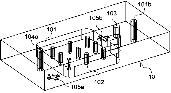
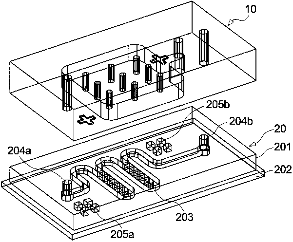
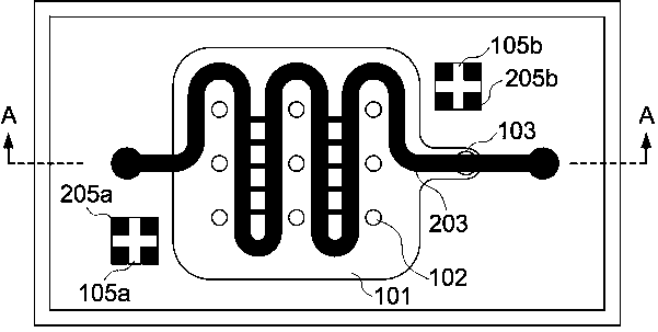
[0019] see Figure 1~Figure 4 . It should be noted that the diagrams provided in this embodiment are only used to illustrate the basic principles, component structures, working processes and effects of the present invention, so that only the components related to the present invention are shown in the diagrams rather than according to the actual The number, formation and dimensional drawing of components during implementation, the type, quantity and ratio of each component may be changed during actual implementation, and the layout of components may also be more complex.

[0020] Such as Figure 1~Figure 4 As shown, the present embodiment provides a structure and method for gas removal in a microfluidic channel. The basic structure of the gas removal structure 10 includes a cavity area 101, a cavity support structure 102, and an air extraction port 10...


PUM


Abstract

The invention discloses a device for removing gas in a micro-fluid passageway. The device comprises the micro-fluid passageway (203). A cavity area (101) for absorbing the gas in the micro-fluid passageway (203) is arranged outside the micro-fluid passageway (203). The cavity area (101) is provided with an extraction opening (103) used for extracting gas to form a vacuum environment. Through the device, bubbles, of various sizes, adsorbed to the wall of the micro-fluid passageway can be removed in the process of using a micro-fluidic chip for loading a liquid sample at the initial phase of a fluid experiment, the bubbles introduced during fluid conveying can be removed in real time in the long-time experiment process through the micro-fluidic chip, and meanwhile it is avoided that the gas precipitating out of fluid gathers to form the bubbles; the device can be easily integrated with the PDMS micro-fluidic chip, and the bubbles in the micro-fluid passageway can be effectively removed and prevented from being generated, so that a pure liquid environment of the micro-fluid passageway is maintained, and long-process stability and accuracy of organism culture on the micro-fluidic chip and micro-observation are guaranteed.

Description

technical field [0001] The invention discloses a device for removing gas in a microfluidic channel, which belongs to the technical field of microfluidics. Background technique [0002] Microfluidics refers to the science and technology involved in systems that use microfluidic channels (tens to hundreds of microns in size) to process or manipulate tiny fluids (picoliters to nanoliters in volume). , chemistry, microelectronics, materials science, biology and biomedical engineering emerging interdisciplinary. Because this technology has the characteristics of miniaturization and integration, the system containing microfluidic channels is usually called a microfluidic chip, also known as a laboratory on a chip or a micro-total analysis system. Microfluidic technology has great development potential and broad application prospects in biomedical research. [0003] In the process of living cells, tissues, embryos, etc. in the microfluidic channel of the microfluidic chip, there ...

Claims


Application Information

Patent Timeline
Patent Type & Authority Patents(China)
IPC IPC(8): G01N1/34
CPCG01N1/34
Inventor 朱真袁璋诣许轩臻
Owner SOUTHEAST UNIV
Why Eureka
Try Eureka