Coupled photon-plasmon micro cavity with focused energy, preparation method and applications thereof

A technology of plasmons and surface plasmons, applied in optical components, optical, electrical components, etc., can solve the problems of large absorption loss of metal structures, focusing coupling, and low utilization rate of incident light sources, etc., to improve the magnetic field strength , the effect of improving the sensitivity

Active Publication Date: 2016-08-31
PEKING UNIV
View PDF5 Cites 22 Cited by
  • Summary
  • Abstract
  • Description
  • Claims
  • Application Information

AI Technical Summary

Problems solved by technology

However, in the SPP focusing process, the absorption loss of the metal structure is relatively large, that is, the quality factor Q is small, and the utilization rate of the incident light source is not high
In addition, how to further couple the focused energy out of the metal structure for utilization is also a major difficulty

Method used


Image

  • Coupled photon-plasmon micro cavity with focused energy, preparation method and applications thereof
  • Coupled photon-plasmon micro cavity with focused energy, preparation method and applications thereof
  • Coupled photon-plasmon micro cavity with focused energy, preparation method and applications thereof

Examples


Embodiment 1

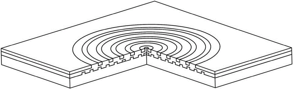
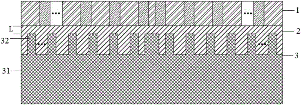
[0028] In this embodiment, the wavelength of incident light is 850 nm. As shown in Figure 1, the coupled photon-plasmon microcavity of this embodiment includes: Bragg nanometer microcavity 1, coupling layer 2 and metal surface plasmon lens 3; wherein, the central dielectric cylinder and the periphery are two different Dielectric concentric rings with alternating refractive indices constitute the Bragg nano-cavity 1, and the refractive index and ring width of the two dielectric rings meet the Bragg reflection conditions; the metal surface plasmon lens 3 includes a substrate and a substrate on the substrate. The central metal cylinder and the concentric metal rings arranged periodically on the periphery; the Bragg nano-cavity and the metal surface plasmon lens are connected by a coupling layer, and the coupling layer 2 fills the gap between the concentric metal rings, and the upper surface is high The distance from the upper surface of the concentric metal ring is L.

[0029] S...

Embodiment 2

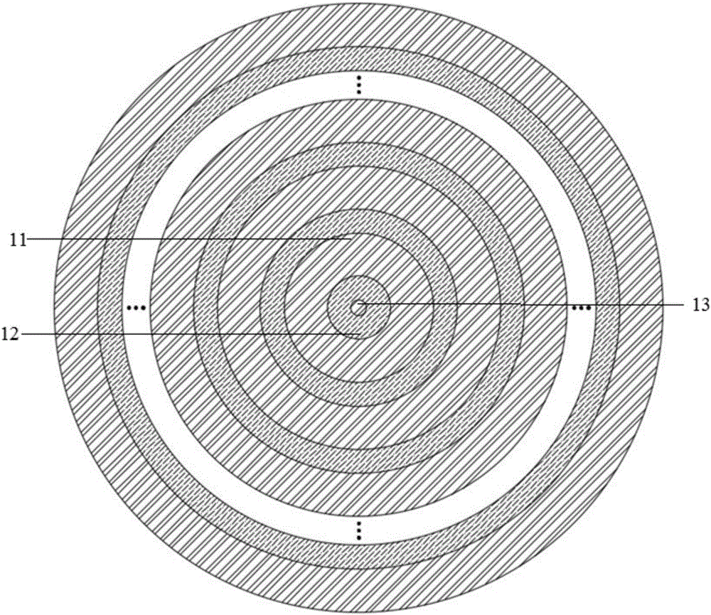
[0036] In this embodiment, the wavelength of incident light is 1620 nm. The period of the two concentric dielectric rings with different refractive indices that the Bragg nano-microcavity includes is 1400nm; the diameter of the dielectric cylinder 13 of the first dielectric in the center of the Bragg nano-micro-cavity is 400nm; the first concentric dielectric ring 11 The width is 900 nm; the width of the second concentric dielectric ring 12 is 500 nm. The distance L between the upper surface of the coupling layer 2 and the surface of the concentric metal ring is 250 nm. The period of the metal ring 32 of the metal surface plasmon lens 3 is 1000nm, the width is 400nm, and the diameter of the innermost metal cylinder is 700nm; the distance between the innermost central cylinder and the innermost metal ring is 300nm. Others are the same as Example 1.

[0037] The size parameters of the bowtie nanoantenna placed on the energy-focused coupled photon-plasmon microcavity of this em...


PUM


Abstract

The invention discloses a coupled photon-plasmon micro cavity with focused energy, a preparation method and applications thereof. A coupled layer is connected with a Bragg nano micro cavity and a metal surface plasmon lens to form a coupled photon-plasmon micro cavity, under effects of the coupled layer, a waveguide mode and a surface Plasmon mode interact, a coupled photon-plasmon mode is formed, and thus, energy is focused in the center of the Bragg nano micro cavity; through a bow tie antenna and a magnetic oscillator, energy limited in the Bragg nano micro cavity can be effectively coupled in the bow tie antenna or the magnetic oscillator, and the electric field strength in the bow tie nano antenna and the magnetic field strength in the magnetic oscillator are greatly improved; and the coupled photon-plasmon micro cavity can be applied to a single molecule Raman spectrum detection device, a molecular surface enhanced infrared absorption spectrum detecting device, a nano point light source in lithography micromachining, and a refractive index sensor or a biosensor.

Description

technical field [0001] The invention relates to a micro-nano-scale optical device, in particular to an energy-focused coupled photon-plasmon microcavity and a preparation method and application thereof. Background technique [0002] At present, the electromagnetic field focusing of surface plasmon polaritons SPPs is mainly achieved by converging the SPPs generated by designing metal structures or adjusting the incident light source to achieve energy focusing. However, in the SPP focusing process, the absorption loss of the metal structure is relatively large, that is, the quality factor Q is small, and the utilization rate of the incident light source is not high. In addition, how to further couple the focused energy out of the metal structure for utilization is also a major difficulty. Contents of the invention [0003] The present invention aims to form a coupled photon-plasmon nano-micro-cavity by coupling a ring-shaped dielectric Bragg (Bragg) nano-micro-cavity and a ...

Claims


Application Information

Patent Timeline
Patent Type & Authority Applications(China)
IPC IPC(8): G02B5/00H01Q15/02H01Q15/08
CPCG02B5/008H01Q15/02H01Q15/08
Inventor 侯玉敏李伟
Owner PEKING UNIV
Why Eureka
Try Eureka