Confocal waveguide broadband input coupling device

An input coupling and waveguide technology, applied in the microwave field, can solve the problems of low coupling efficiency in working mode, low coupling efficiency, and insufficient bandwidth, and achieve the effect of widening bandwidth, high coupling efficiency, and improving performance

Active Publication Date: 2016-08-31
UNIV OF ELECTRONICS SCI & TECH OF CHINA
View PDF5 Cites 10 Cited by
  • Summary
  • Abstract
  • Description
  • Claims
  • Application Information

AI Technical Summary

Problems solved by technology

Whether it is (I), or (II), (III) structure, its bandwidth is relatively narrow, its coupling efficiency is relatively low, the relative bandwidth is about 5%, and the coupling efficiency is up to 70%.
The main reasons for the insufficient bandwidth and low coupling efficiency of the working mode are: part of the energy injected from the input waveguide is reflected from the input waveguide; part of the energy of the working mode is diffracted from the lateral open surface of the input coupling system; in the input coupling system In addition to the operating mode, there are many parasitic modes; for a structure injected with energy by two symmetrical input waveguides, there is also the problem of energy transmission out of the symmetrical waveguides

Method used


Image

  • Confocal waveguide broadband input coupling device
  • Confocal waveguide broadband input coupling device
  • Confocal waveguide broadband input coupling device

Examples


Embodiment Construction

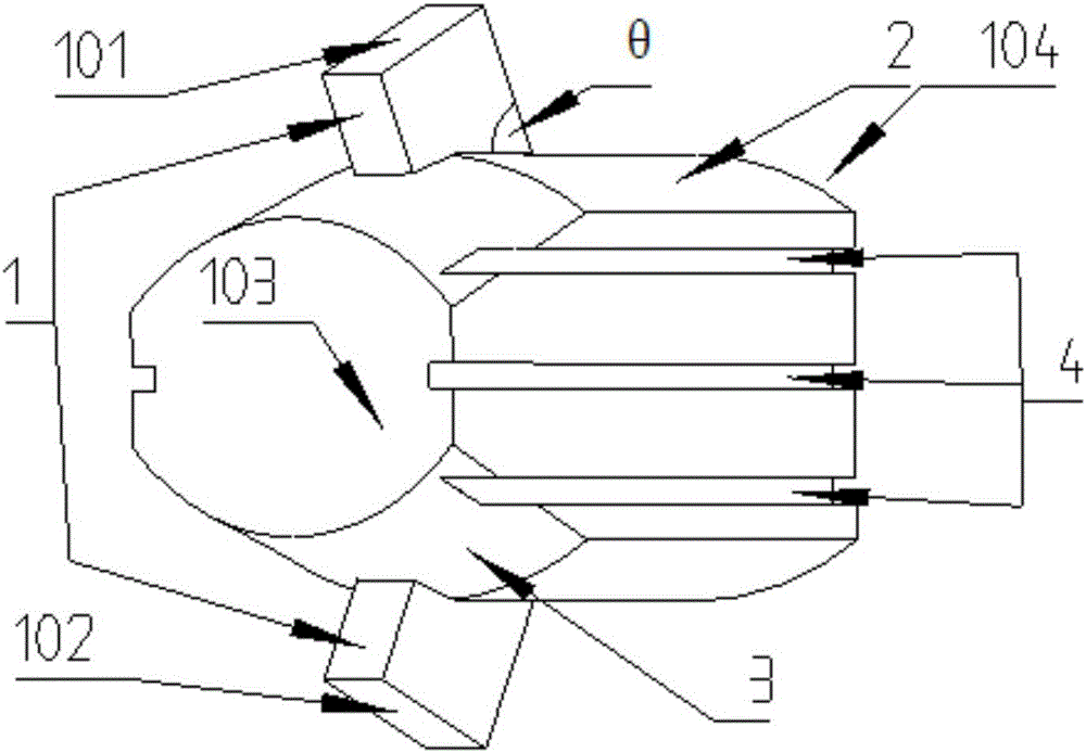
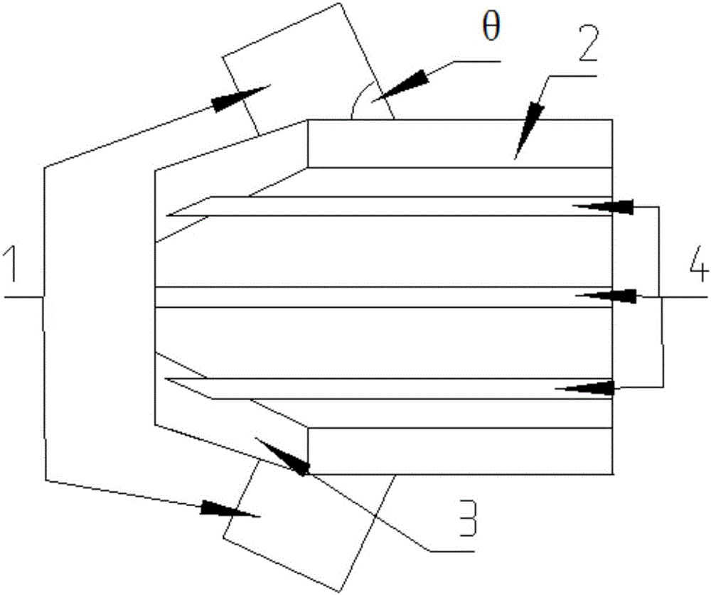
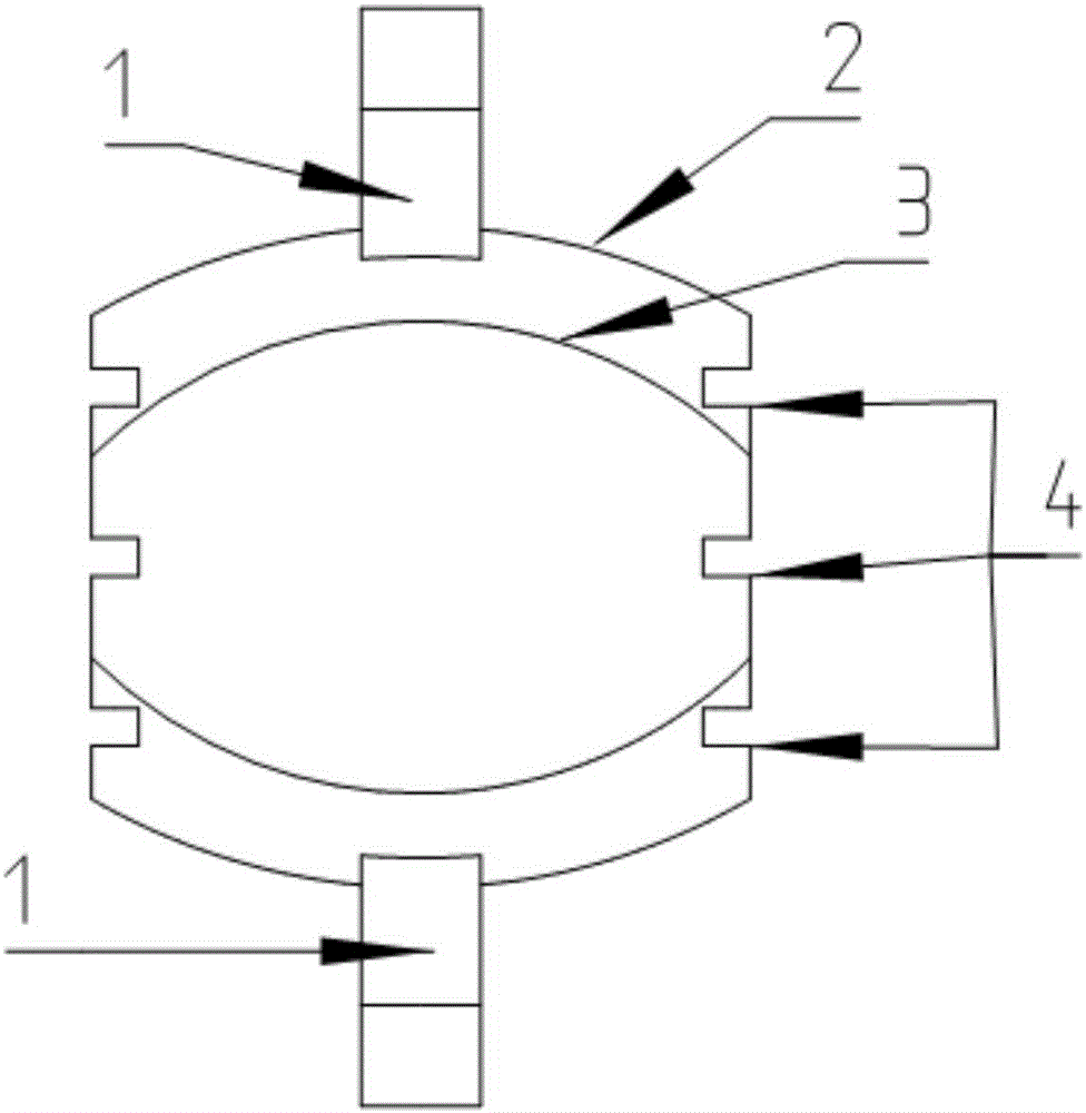
[0025] The present invention will be further described in detail below in conjunction with a design example of a new confocal waveguide gyrotraveling wave tube input coupling system working in the W band and the accompanying drawings. Due to the narrow bandwidth of the traditional confocal waveguide input structure, the coupling efficiency is low, especially the transmission in the high frequency band drops sharply. It can be solved by making a certain frequency point f in the high frequency band, so that the transmission condition of the electromagnetic wave input into the waveguide (1) is the same as that in the confocal waveguide at this frequency point. In the confocal waveguide, the electromagnetic wave propagates forward by continuous reflection between the two mirrors, so the propagation velocity of the electromagnetic wave and the group velocity form an angle θ, so as long as the input waveguide (1) and the confocal waveguide (2 ) is the same as the included angle θ be...


PUM


Abstract

The invention discloses a confocal waveguide broadband input coupling device, and relates to the technical field of microwave and millimeter wave devices, specifically a novel confocal waveguide gyro-TWT (standing wave tube) broadband input coupling device, wherein the device can be used for a gyro-TWT at a millimeter wave band and terahertz wave band. There are also many parasitic modes in a confocal waveguide broadband input coupling system, thereby causing the decrease of the coupling efficiency. Therefore, the device inhibits the parasitic modes through changing the boundary conditions, and enables the more power inputted by standard waveguides to be coupled to the power in a working mode. An opening surface of the confocal waveguide broadband input coupling system is sealed, and the sealed surface is slotted, thereby changing the boundary conditions, inhibiting the parasitic modes, enabling the coupling efficiency of the working mode to be higher, and enabling the coupling bandwidth to be greater.

Description

technical field [0001] The invention relates to the technical field of microwave and millimeter wave devices, in particular to a novel confocal waveguide gyrotraveling wave tube broadband input coupling system, which can be applied to gyrotraveling wave tubes in the millimeter wave and terahertz bands. Background technique [0002] The gyrotron is a new type of high-power millimeter-wave device with high power, high efficiency, high gain and a certain bandwidth. It has important application prospects in high-resolution millimeter-wave imaging, millimeter-wave countermeasures, electronic warfare, and microwave communication systems. The input coupler is one of the core components of the gyrotron TWT. It converts the high-frequency signal input by the waveguide into the standing wave field of the working mode in the high-frequency structure. Due to the relativistic mass effect, it gradually forms angular clustering. - Hand over energy in the wave interaction to produce high p...

Claims


Application Information

Patent Timeline
Patent Type & Authority Applications(China)
IPC IPC(8): H01J23/38
CPCH01J23/38
Inventor 王建勋姚叶雷夏建波任绪迅罗勇
Owner UNIV OF ELECTRONICS SCI & TECH OF CHINA
Why Eureka
Try Eureka