Grinding method for numerical-control worm grinding wheel of cycloid gear

A worm grinding wheel, cycloid gear technology, applied in the direction of elements with teeth, belts/chains/gears, gear teeth, etc., can solve the problem of high precision grade indexing accuracy requirements, unsatisfactory effects, and reduced grinding accuracy and other problems, to achieve the effect of ensuring machining accuracy and stability, convenient, accurate and fast trimming, and reducing auxiliary time.

Active Publication Date: 2016-09-07
CHONGQING UNIV
View PDF10 Cites 16 Cited by
  • Summary
  • Abstract
  • Description
  • Claims
  • Application Information

AI Technical Summary

Problems solved by technology

[0003] The development of form grinding technology for cycloidal gears is relatively mature, and the production efficiency cannot be guaranteed. Although the solution of modifying the tool and processing multiple teeth at the same time is proposed, the effect is not satisfactory; (mainly including positioning installation, tool setting accuracy and indexing accuracy) have high requirements, which also limits the development of cycloidal gear form grinding
[0004] The cycloidal gear grinding machine adopts the motion relationship between the gear and the pin wheel to realize the grinding of the cycloidal gear when the cycloidal gear reducer is working. Although this method realizes continuous grinding, the processing efficiency is still relatively low.
[0005] The cycloidal worm grinding wheel grinding technology researched by Xu Youfu, Wang Shizheng, etc., uses

Method used


Image

  • Grinding method for numerical-control worm grinding wheel of cycloid gear
  • Grinding method for numerical-control worm grinding wheel of cycloid gear
  • Grinding method for numerical-control worm grinding wheel of cycloid gear

Examples


Embodiment Construction

[0033] The present invention will be described in further detail below in conjunction with the accompanying drawings and specific embodiments.

[0034] Taking the grinding of a standard involute helical gear by a worm grinding wheel as an example, a numerical control worm grinding wheel grinding method of a cycloidal gear comprises the following steps:

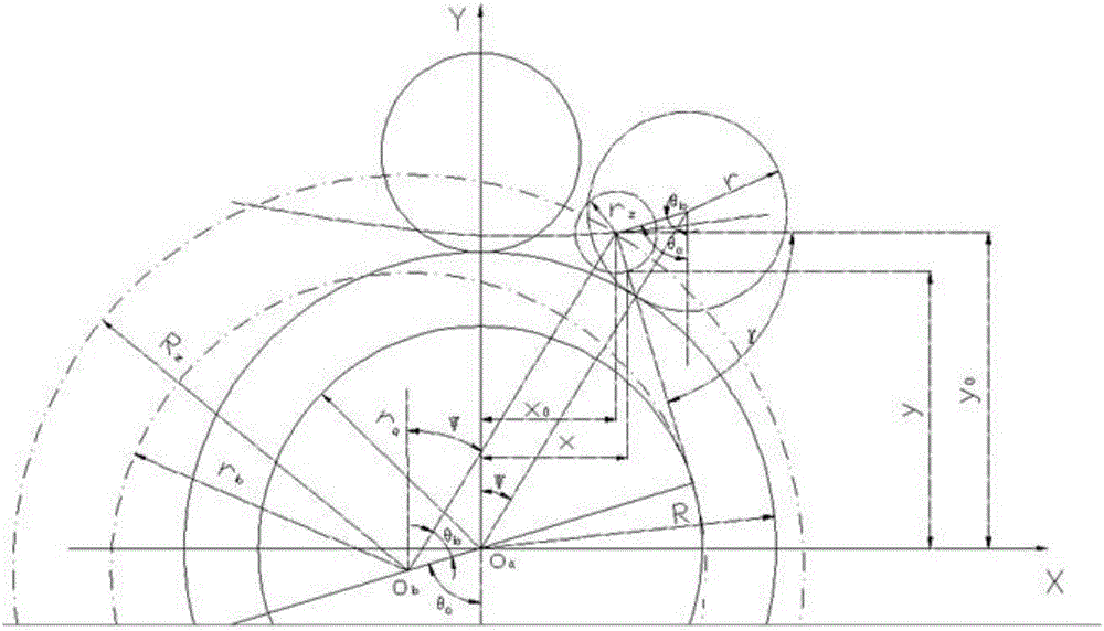
[0035] Such as figure 1 As shown, the parameters in the figure are:

[0036] R Z is the pinwheel radius;

[0037] K 1 is the short-amplitude coefficient of the cycloid;

[0038] Z b is the number of pinwheel teeth;

[0039] Z a is the number of cycloid gear teeth;

[0040] ψ is the rotation angle of r relative to R (without enveloping method);

[0041] x 0 、y 0 is the cycloid gear tooth profile equation;

[0042] x and y are the profile equations of the cycloid equidistant line.

[0043] From the formation process of the cycloid, the geometric relationship can be used to obtain the tooth profile equation of the cy...


PUM


Abstract

The invention relates to a grinding method for a numerical-control worm grinding wheel of a cycloid gear. The space engagement theory is utilized, the three-dimensional profile equation of the worm grinding wheel of the machined cycloid gear is deduced according to the three-dimensional profile equation of the cycloid gear, and the cycloid gear is subjected to fine polishing through the worm grinding wheel. The grinding method has remarkable advantage compared with a cycloid gear forming and grinding technique, and intermittent machining is replaced by continuous machining. Meanwhile, the generating motion precision stability is higher than the intermittent Intermittent precision, so that the gear polishing precision is remarkably improved, the gear polishing production cost is remarkably reduced, and the gear polishing efficiency is remarkably improved. The grinding method is applied to a machine tool used for grinding the cycloid gear through the worm grinding wheel, a special clamp table for corresponding workpieces is designed, two cycloid gear blanks are positioned and installed at a time, and the spatial positions of the two cycloid gear blanks are determined. An online measuring head is additionally arranged on one side of the worm grinding wheel so as to position the spatial position of the worm grinding wheel. By means of the combination of the two techniques, rapid and accurate tool setting of the cycloid gear blanks and the worm grinding wheel is achieved.

Description

technical field [0001] The invention belongs to the field of gear grinding in the field of mechanical manufacturing, in particular to the field of cycloidal gear generation grinding, and relates to a numerically controlled worm grinding wheel grinding method for cycloidal gears. Background technique [0002] With the development of industrial technology, more and more cycloidal gears are used. Cycloidal gear reducers have the advantages of large reduction ratio and compact structure. There are important applications in the transmission mechanism of robots. With the development of the robot industry, the quantity and quality of cycloid gears also need to be further improved; Cycloidal gears are required to continuously improve the efficiency and accuracy level of finishing. [0003] The development of form grinding technology for cycloidal gears is relatively mature, and the production efficiency cannot be guaranteed. Although the solution of modifying the tool and processin...

Claims


Application Information

Patent Timeline
IPC IPC(8): B23F5/04
CPCB23F5/04
Inventor 李国龙何坤赵君
Owner CHONGQING UNIV
Why Eureka
Try Eureka