
Dragon bone waterlift type earthwork conveying system and construction method thereof

A conveying system and a waterwheel-type technology, which is applied to earth movers/shovels, construction, etc., can solve the problems of long dehydration and consolidation period of air-tight earthwork, high moisture content of conveying silt, and limited conveying distance, etc., and achieve shortening Consolidation and dehydration time, low moisture content of sludge, and the effect of increasing the conveying distance

Inactive Publication Date: 2016-09-07
宁波弘海众创空间服务有限公司 +2
View PDF5 Cites 2 Cited by
  • Summary
  • Abstract
  • Description
  • Claims
  • Application Information

AI Technical Summary

Problems solved by technology

[0003] The existing earthwork construction equipment mainly includes piston-type sludge conveying pump and truss-type earthwork conveying equipment, etc.; the construction efficiency of the piston-type sludge conveying pump is relatively high, and the conveying distance is relatively long. However, due to the disturbance of the sludge before pumping, the piston The moisture content of the sludge transported by the silt transport pump is relatively high, resulting in a long dehydration and consolidation cycle of the air-tight earthwork, which affects the construction period. Although the truss-type earthwork conveying equipment does not increase the moisture content of the silt, the construction efficiency is low and the transportation distance is limited. , therefore, in order to meet the demand for soil extraction from seawall air-tight earthworks, it is urgent to develop a conveying system that can transport earthworks over long distances

Method used


Image

  • Dragon bone waterlift type earthwork conveying system and construction method thereof
  • Dragon bone waterlift type earthwork conveying system and construction method thereof
  • Dragon bone waterlift type earthwork conveying system and construction method thereof

Examples


Embodiment 1

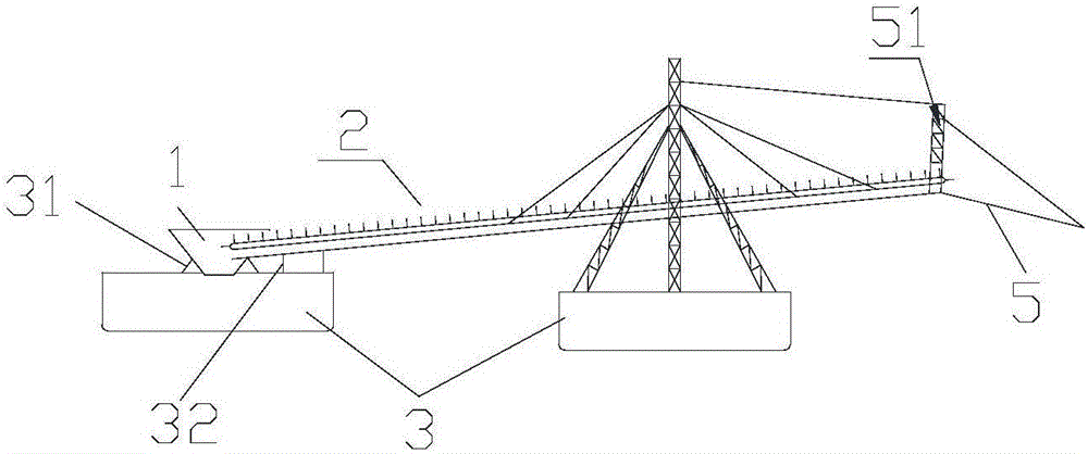
[0030] see figure 1 , Figure 4 with Figure 5 As shown, they are respectively the sectional view of the keel waterwheel type earthwork conveying system in Embodiment 1 of the present invention, the front view of the conveyor and the sectional view of the conveyor.

[0031] A keel waterwheel type earthwork conveying system includes a first-stage conveying unit, the conveying unit includes a collector 1 and a conveyor 2, and the collector 1 and the conveyor 2 both use a floating tank 3 as a fulcrum, the The end of the conveyor 2 is placed in the collector 1, the conveyor 2 includes a tank body 21 and a conveyor belt 22, the conveyor belt 22 is provided with a scraper 221, and the conveyor belt 22 is transported from above The upper conveyor belt is placed on the tank body 21 through the support shaft 23, and the lower conveyor belt is placed in the tank body 21, wherein the conveyor belt 2 is supported. The number of floating tank 3 is at least one.

[0032] In this embodim...

Embodiment 2

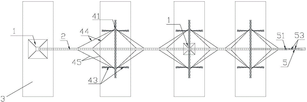
[0035] A kind of keel waterwheel type earthwork conveying system as mentioned above, the difference of this embodiment is that, as figure 2 , Figure 4 with Figure 5 As shown, they are respectively the sectional view of the keel waterwheel type earthwork conveying system in the second embodiment of the present invention and the structural schematic diagram of the conveyor.

[0036] A keel waterwheel type earthwork conveying system, comprising two-stage conveying units, respectively a first-stage conveying unit and a second-stage conveying unit, both of the first-stage conveying unit and the second-stage conveying unit include a collector 1 and conveyor 2, both of the collector 1 and the conveyor 2 use the floating tank 3 as a fulcrum, the end of the conveyor 2 is placed in the collector 1, and the conveyor 2 includes a tank 21 and a conveyor belt 22, the conveyor belt 22 is provided with a scraper 221, the conveyor belt is composed of an upper conveyor belt and a lower con...

Embodiment 3

[0039] A kind of keel waterwheel type earthwork conveying system as mentioned above, the difference of this embodiment is that, as Image 6 As shown, it is a structural schematic diagram of the skeleton of the conveyor belt of the present invention. The conveyor belt 22 is formed by connecting several skeletons 222 through fasteners 223. The scraper 221 is arranged on the skeleton 222 and the scraper The size of 221 matches the size of the tank body 21, so that when the scraper 221 scrapes the sludge in the tank body 21, the sludge scraped by the scraper 221 can be transported to the tank The end of the body 21, wherein the fastener 223 is a screw, a bolt or a pin, which is convenient for installation and disassembly. In this embodiment, the length of the transmission belt can be changed by increasing or decreasing the number of the skeletons 222 according to the actual situation.

[0040] Preferably, the scraper 221 is arranged vertically to the frame 222 and the scraper 221...


PUM


Abstract

The invention provides a dragon bone waterlift type earthwork conveying system and a construction method thereof. The dragon bone waterlift type earthwork conveying system comprises at least one segment of conveying unit; each segment of conveying unit comprises a material collector and a conveyer which both adapt buoyancy boxes as fulcrums; the end portion of each conveyer is arranged in the corresponding material collector; each conveyer comprises a groove body and a conveying belt; each conveying belt is provided with a scraping board; each conveying belt is composed of an upper conveying belt body and a lower conveying belt body; each upper conveying belt body is arranged on the corresponding groove body through a supporting shaft; each lower conveying belt body is arranged in the corresponding groove body; and the size of each scraping board is matched with that of the corresponding groove body. The dragon bone waterlift type earthwork conveying system has the beneficial effects that each supporting shaft is arranged below the corresponding upper conveying belt body and can be used for supporting the weight of the upper conveying belt body, due to the arrangement of the supporting shafts, the length of the conveying belt in each stage of conveying unit is increased, besides, continuous conveying is achieved between the conveyers, power transmission is fast, and the conveying efficiency is improved.

Description

technical field [0001] The invention relates to an earthwork conveying system, in particular to a keel waterwheel type earthwork conveying system and a construction method thereof for earthwork fetching from air-tight earthwork of seawalls. Background technique [0002] With the contradiction between the rapid development of coastal economy and the shortage of land resources becoming more and more prominent, the speed of tidal flat reclamation is getting faster and faster, and the space is gradually developing from shallow to deep water, and tidal flat operations are gradually changing to water operations. It is carried out in tidal flats far away, and then long-distance transportation has become a major difficulty in earthwork construction. [0003] The existing earthwork construction equipment mainly includes piston-type sludge conveying pump and truss-type earthwork conveying equipment, etc.; the construction efficiency of the piston-type sludge conveying pump is relative...

Claims


Application Information

Patent Timeline
IPC IPC(8): E02F7/00
CPCE02F7/00
Inventor 冯宇张晓锋林涛吴金胜郁建红曹俊杰
Owner 宁波弘海众创空间服务有限公司
Learn More