Fabrication method of fabric stretch sensor

A sensor and fabric technology, applied in the field of functional textiles and smart textiles, to achieve the effects of wide application prospects, small dielectric constant, and low product cost

Inactive Publication Date: 2018-06-26
DONGHUA UNIV
View PDF8 Cites 0 Cited by
  • Summary
  • Abstract
  • Description
  • Claims
  • Application Information

AI Technical Summary

Problems solved by technology

This kind of sensor overcomes the shortcomings of early sensors that cannot be folded and cannot be cleaned, but this structure still embeds single-function sensing elements and sending and receiving signal elements into textiles.

Method used


Image

  • Fabrication method of fabric stretch sensor
  • Fabrication method of fabric stretch sensor
  • Fabrication method of fabric stretch sensor

Examples


Embodiment 1

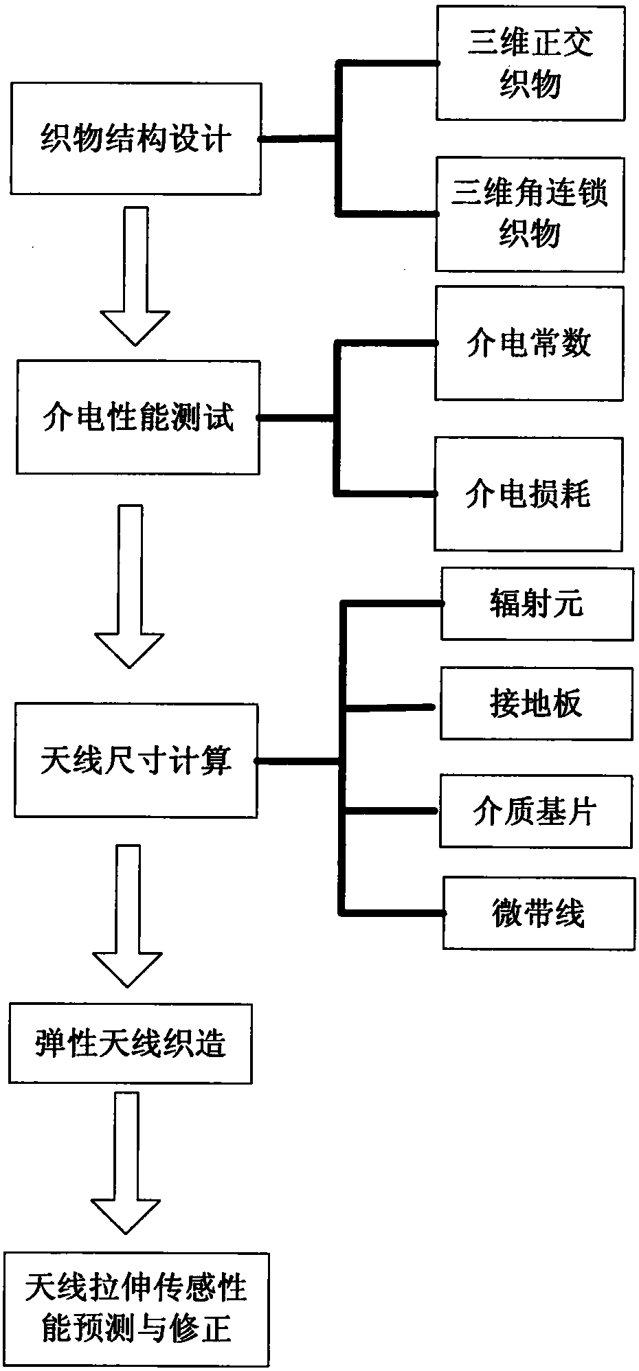
[0037] combine figure 1 , the preparation of three-dimensional orthogonal structure tensile sensing antenna fabric, the specific method is as follows:

[0038] (1) Select the silver-plated elastic polyester yarn as the conductive yarn, carry out chemical silver plating under the pre-stretched 50% situation of the elastic polyester yarn (U.S. DuPont Company) with a fineness of 400dtex, and make the yarn retract after the silver plating ends to obtain Stretchy conductive polyester yarn.

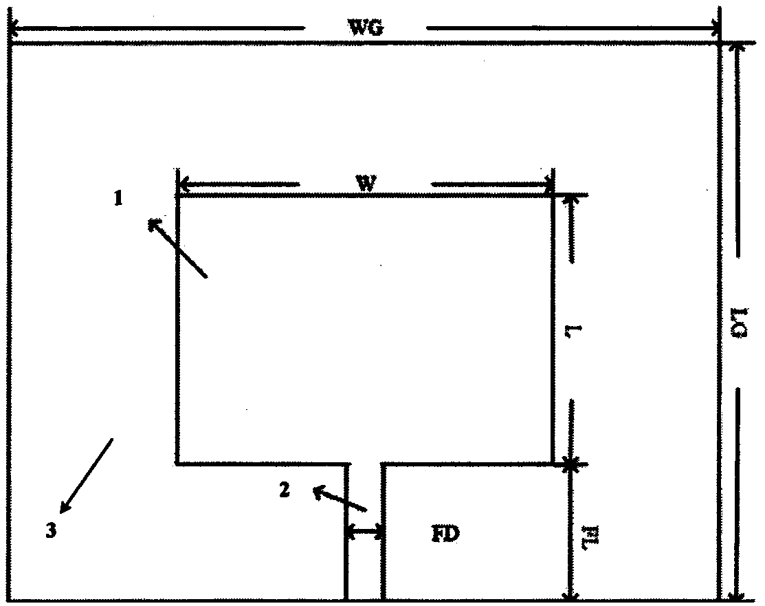
[0039] (2) The operating frequency of the designed antenna is 2.5 GHz, the thickness of the prepared three-dimensional fabric is 1.5 mm, and its dielectric constant r=2, according to the antenna design theory (see Chapter 6 of "Antenna Theory and Technology", edited by Zhong Shunshi) The size parameters of the single radiating element microstrip antenna are calculated; for example figure 2 shown. figure 2 Among them, 1 is the radiating element, 2 is the feeding line, and 3 is the substrate...

Embodiment 2

[0045] The preparation of stretch sensing antenna fabric based on carbon tube coated yarn, the specific method is as follows:

[0046] (1) Multi-wall carbon nanotube coated spandex yarn (Jiangsu Qiaoxin Fiber Co., Ltd.) with a fineness of 560 dtex was selected as the elastic conductive yarn. When the spandex yarn is pre-stretched by 50%, it is immersed in the aqueous dispersion of multi-walled carbon nanotubes (Chengdu Organic Chemistry Co., Ltd., Chinese Academy of Sciences), and the pre-stretching force is released after the water is dried and volatilized to make the yarn retract Elastically stretchable conductive yarns are obtained.

[0047](2) The operating frequency of the antenna is designed to be 3GHz, the thickness of the prepared three-dimensional fabric is 1.3mm, and its dielectric constant r=2. According to the antenna design theory, the size parameters of the microstrip antenna with single radiating element are calculated, such as figure 2 shown. figure 2 Among...


PUM

PropertyMeasurementUnit
thicknessaaaaaaaaaa
thicknessaaaaaaaaaa
elongation at breakaaaaaaaaaa

Abstract

The invention provides a preparation method for a fabric tension sensor. The preparation method comprises the following steps: selecting a high-elasticity yarn, weaving a fabric from the yarn, using the fabric as a medium substrate for an antenna and testing and calculating the dielectric constant and dielectric loss of the fabric; calculating the basic size of a radiation element of the antenna according to calculation results obtained in the previous step and work frequency needed by the antenna and weaving the radiation element, a feeder line and an earth plate of the antenna from an elastic conductive yarn and the high-elasticity yarn; and carrying out vertical binding of the yarns and weaving an integral fabric antenna structure from each part, wherein when the fabric antenna structure suffers tensile deformation, frequency changes are obvious and present a linear rule. According to the invention, a fabric structure prone to tensile deformation is combined together with an antenna element, thereby obtaining a tension sensing fabric with both a wireless signal transmission function and a tension sensing function; the sensing fabric has good structural integrity and has the characteristic of stable, uniform and predicable deformation under the action of outside force; and the prepared fabric tension sensor is low in cost, stable in performance and favorable for promotion and application.

Description

technical field [0001] The invention relates to a preparation method of a fabric tension sensor, which belongs to the technical field of functional textiles and intelligent textiles. Background technique [0002] With the development of science and technology, information science, material science and other related technologies have been continuously developed and integrated with traditional textiles. Textiles have broken through the original use of heat preservation and beautification. On the premise of maintaining the original properties of textiles, they are moving towards functional and The development of intelligence has endowed textiles with unique functions, and gradually entered a new era of intelligent textiles. The combination of traditional clothing textiles and interdisciplinary subjects such as electronic information, semiconductors, and radio communications has become a meeting point between traditional industries and high-tech, laying a solid foundation for th...

Claims


Application Information

Patent Timeline
Patent Type & Authority Patents(China)
IPC IPC(8): G01N27/00
CPCG01N27/00
Inventor 许福军王义斌朱鸿飞谢惺
Owner DONGHUA UNIV
Why Eureka
Try Eureka