
Relative position measurement method through radio positioning and measurement device thereof

A radio positioning and relative position technology, applied in radio wave measurement systems, measurement devices, positioning and other directions, can solve the problems of short pulse width modulation bandwidth, low positioning accuracy, and high difficulty in system implementation, and achieve simple implementation, high reliability, and high reliability. The effect of simplifying the wireless positioning ranging method

Active Publication Date: 2016-09-07
长沙深之瞳信息科技有限公司
View PDF4 Cites 9 Cited by
  • Summary
  • Abstract
  • Description
  • Claims
  • Application Information

AI Technical Summary

Problems solved by technology

Among them, RSSI is easily affected by environmental factors, with serious multipath interference and low positioning accuracy; while AOA can provide azimuth information, but cannot obtain distance information, so it cannot obtain accurate three-dimensional relative positional relationship; the principle of TOA ranging is by measuring electromagnetic wave propagation If the ranging accuracy is required to be high, the pulse width must be very short or the modulation bandwidth is very wide. The system implementation is very difficult, and precise time synchronization between the base station and the mobile node is required; similarly, although TDOA is relaxed The time synchronization requirements between the base station and the mobile node are met, but there is also the problem that the system is difficult to implement when the ranging accuracy is high; in PDOA, if the principle of multi-station radar ranging is used, the transceiver measures two receiving antennas at different positions. Signals can be used to calculate the direction of signal propagation through their phase difference, but they do not have ranging capabilities; if according to the principle of multi-frequency radar ranging, the same antenna produces different phase delays for continuous waves with different transmitting fixed frequencies, by solving phase difference to calculate distance
Both methods produce phase entanglement, which requires a more complex phase defuzzification algorithm, and requires the transmission and reception of several point-frequency signals that are very close together, and the system implementation is also very difficult

Method used


Image

  • Relative position measurement method through radio positioning and measurement device thereof
  • Relative position measurement method through radio positioning and measurement device thereof
  • Relative position measurement method through radio positioning and measurement device thereof

Examples


Embodiment 1

[0035] Embodiment 1: Relative position measuring method and measuring device for setting at least 3 receiving units

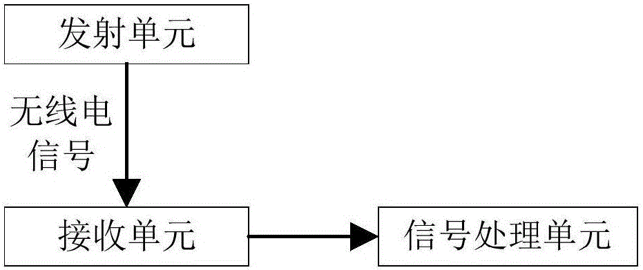
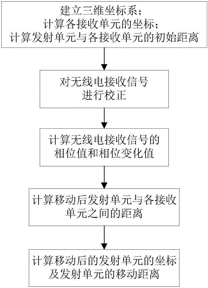
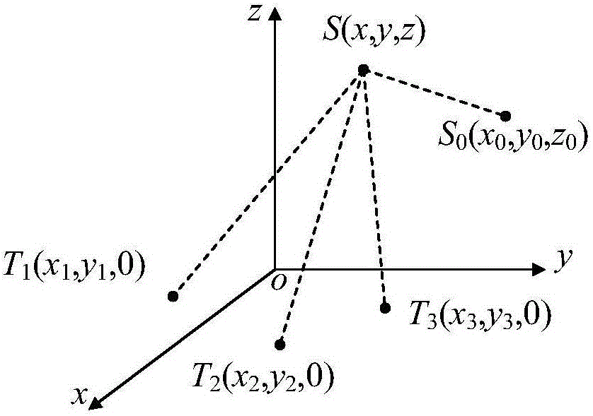
[0036] Such as figure 1 — image 3 As shown, a three-dimensional coordinate system is established with any point as the coordinate origin; the transmitting unit S is installed on the measured object, and the transmitting unit S can transmit a single-frequency radio signal with frequency f, and the transmitting unit moves with the measured object; in the same xoy plane Or set at least 3 receiving units T on the yoz plane or xoz plane i , where i≥3, and at least 3 receiving units are not on the same straight line. The trajectory of the transmitting unit S has continuity, and the transmitting unit S continuously transmits single-frequency radio signals. Through continuous observation, the transmission unit S and each receiving unit T can be obtained. i the distance between.

[0037] Here to set at least 3 receiving units T on the same xoy plane iAs an example...

Embodiment 2

[0056] Embodiment 2: Relative position measuring method and measuring device for setting at least 4 receiving units

[0057] Such as figure 1 , figure 2 and Figure 4 As shown, a three-dimensional coordinate system is established with any point as the coordinate origin; the transmitting unit S is installed on the measured object, and the transmitting unit S can transmit a single-frequency radio signal with a frequency of f, and the transmitting unit moves with the measured object; Set up at least 4 receiving units T i , where i≥4, and at least 3 receiving units are not on the same straight line. The trajectory of the transmitting unit S has continuity, and the transmitting unit S continuously transmits single-frequency radio signals. Through continuous observation, the transmission unit S and each receiving unit T can be obtained. i the distance between.

[0058] (1) Calculate the initial coordinate value and the initial distance between the transmitting unit and each re...

Embodiment 3

[0068] Embodiment 3: Control the moving direction and moving distance of the measured object

[0069]In the actual application process, if it is necessary to obtain real-time and accurate relative position information of the movement of a measured object, or to control the moving direction and moving distance of the measured object, such as fixed-point hovering and automatic retraction, then It is only necessary to arrange the transmitting unit S on the object to be measured, and use the relative position measuring method described in Embodiment 1 or 2 above to obtain real-time relative position information of the object under test moving. When fixed-point hovering is required, measure the relative position information of the object under test in real time. When the object under test reaches the desired position, operate the corresponding control structure to make it stop moving.


PUM


Abstract

The invention provides a relative position measurement method through radio positioning and a measurement device thereof. The measurement device comprises a transmitting unit, receiving units and a signal processing unit. Receiving signals of each receiving unit are extracted by recording the position of each receiving unit, the distance between all the receiving units and the distance between each receiving unit and the transmitting unit under the initial state so as to solve phase information. The position of the transmitting unit relative to a platform can be solved according to the space quadrilateral geometric relation of the receiving units and the transmitting unit. The phase ambiguity problem is solved, and measurement of the direction and the relative position of moving points can be realized through transmitting signals of single frequency so that the system is easy to realize, high in reliability and low in influence of external factors and can control the moving distance and the position of the moving nodes in real time and can be widely applied to the system requiring long-term monitoring and early warning.

Description

technical field [0001] The invention relates to a method and a device for determining a relative position, in particular to a relative position measuring method and a measuring device using radio positioning, which belong to the field of wireless positioning. Background technique [0002] Nowadays, in some fields that require long-term investigation, supervision, communication, search and rescue, patrol, aerial photography, and industrial production, mobile nodes (such as tethered receiving nodes, industrial robot hands) are usually installed on platforms (including ground vehicles, ships, etc.) ships, ground fixed stations, workshops, etc.) on cables or movable arms. In order to facilitate better processing of target information, obtain real-time and accurate relative position information of the mobile node relative to the platform, and control the mobile node, such as fixed-point hovering and automatic retraction, etc., become particularly important. [0003] In recent ye...

Claims


Application Information

Patent Timeline
Patent Type & Authority Applications(China)
IPC IPC(8): G01S5/02
CPCG01S5/0284
Inventor 王雅敏肖平
Owner 长沙深之瞳信息科技有限公司
Learn More